GE HEALTHCARERAFT VOLUSON E8 / VOLUSON E6
D
IRECTION KTD102576, REVISION 7 DRAFT (AUGUST 23, 2012) SERVICE MANUAL
4-16 Section 4-4 - Functional Checks
4-4-4 Spectral Doppler Mode Checks
NOTE: Different menus are displayed depending on which Spectral Doppler Mode (PW or CW) is selected.
NOTE: The Continuous Wave Doppler Mode is an Option. The CW
key is only illuminated if the option is
installed and the selected probe is capable for the Continuous Wave Doppler Mode.
For further details refer to the Voluson E8 / Voluson E6 Basic User Manual.
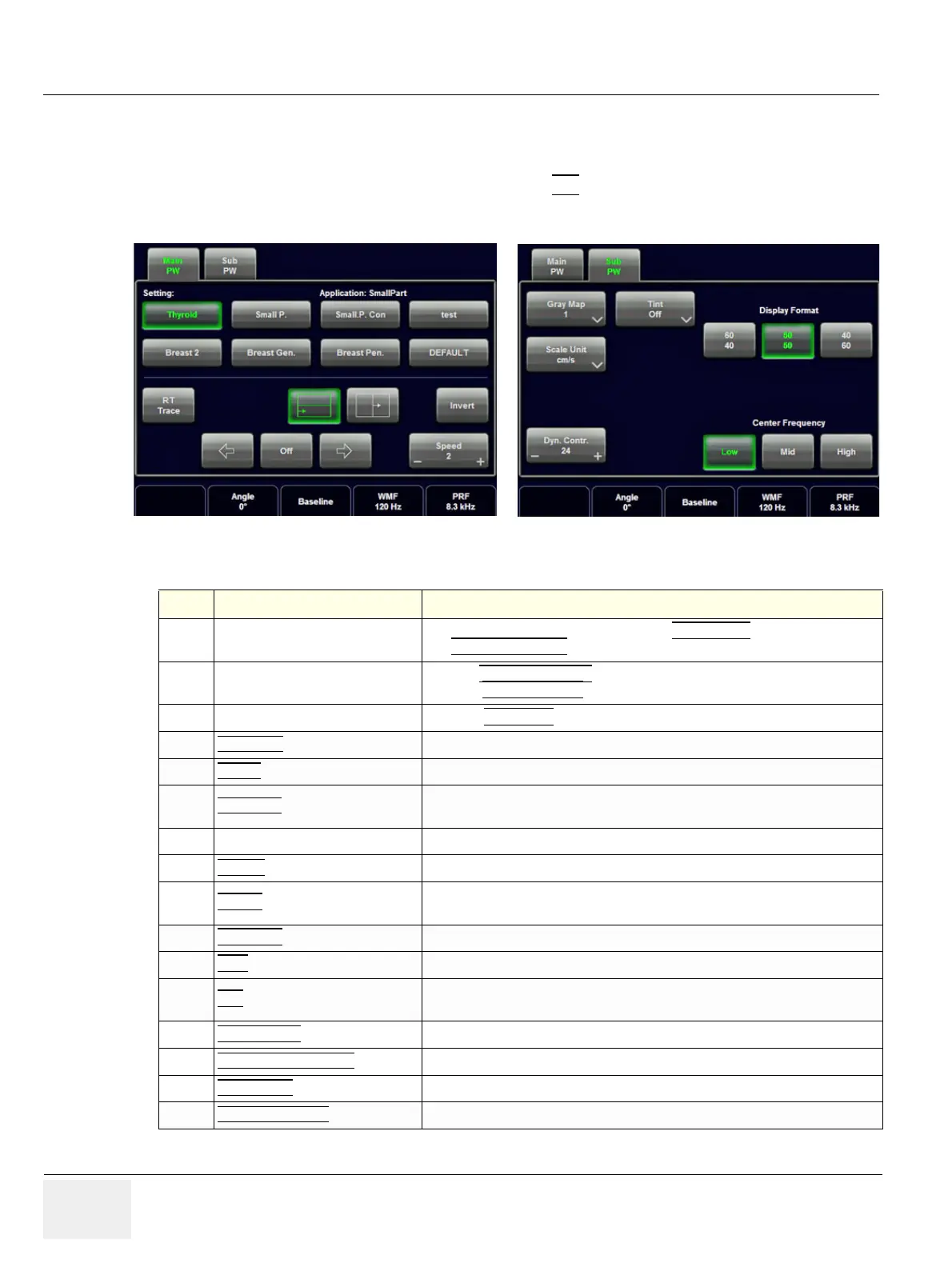
Figure 4-14 PW Main and PW Sub Menu
Table 4-4 Spectral Doppler Mode (PW, CW) Functions
Step Task Expected Results
1
Gate Position and Gate Size
Adjust the Gate- Position resp. Size with the TRACKBALL
in the 2DSingle image.
The upper trackball key
changes from Gate position to Gate size.
2
Activation of Doppler Mode
Press the right trackball key
to activate the motion display.
Press the left trackball key
to activate both Modes (B/D).
3
Doppler Gain Rotate the PW MODE
key to adjust the amplification of the entire spectrum.
4
STEERING The steering function is only available with linear probes.
5
SPEED By touching up or down, four different sweep speeds can be selected.
6
RT TRACE (Real Time Auto-Trace)
The envelope curve of the Doppler spectrum (maximum velocities) and the
corresponding evaluations are automatically displayed on the monitor.
7
Display Format Doppler spectrum is displayed below the B mode image or on its right side.
8
INVERT
To invert the Doppler spectrum display in relation to the direction of the flow.
9
ANGLE
The angle cursor can be turned in both directions without stop. By pressing the
angle knob repeatedly the angle correction switches from +60° to 0° and to -60°.
10
BASELINE Adjusting the baseline is possible in read- and write Mode (up/down in 8 steps).
11
WMF (Wall Motion Filter) Used to eliminate Doppler “noise” that is caused by vessel wall motion.
12
PRF
The Velocity Range display is governed by the pulse repetition frequency (PRF)
Exceeding the maximum PRF, the HPRF-Mode is automatically switched on.
13
DYN. CONTR.
Dynamic Range adjusts the display cutoff of the Doppler analysis waveform.
14
CENTER FREQUENCY
It serves for selection of the required transmit frequency.
15
SCALE UNIT
To select the displayed measuring system (in relation to the zero-line).
16
DISPLAY FORMAT For selection of different rations of display format.