GE HEALTHCAREDRAFT VOLUSON E8 / VOLUSON E6
D
IRECTION KTD102576, REVISION 7 DRAFT (AUGUST 23, 2012) SERVICE MANUAL
Chapter 7 - Diagnostics/Troubleshooting 7-19
Section 7-7
Minimum Configuration to Boot/Scan
7-7-1 Minimum Configuration to Scan
1.) Connect the minimum configuration of cables to scan:
a.) Console
b.) USB UI (User Interface) and USB Hub
c.) Voluson E8: DVI Cable (Digital Visual Interface) from Graphic Card DVI Out to RTV DVI In
Voluson E6: DVI Cable (Digital Visual Interface) from ADD-On DVI Out to RTV DVI In
d.) Monitor
e.) Kontron Dual-Core
BT10 only: RTV
2.) Connect the Mains Power cable and mount the pull-out protection (see: Figure 4-4 on page 4-4).
3.) Connect the Power Cable to an appropriate mains power outlet and switch ON the Circuit Breaker.
4.) Connect a probe.
5.) Press the ON/OFF Standby button on the Control Panel to boot up the System.
6.) Start an User Program.
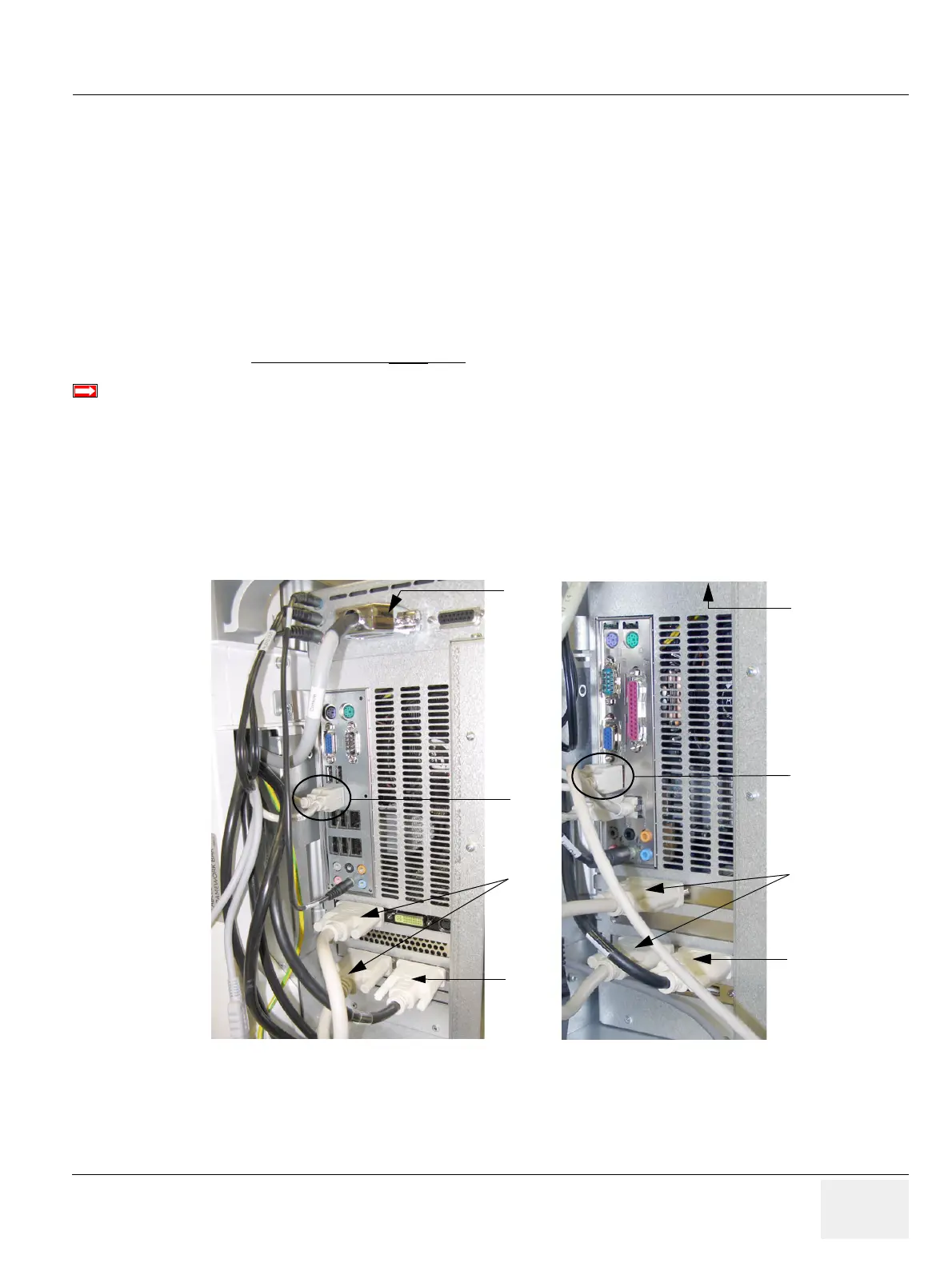
BT-Version:
Please observe that cable-minimum configuration depend on BT version and the currently installed
PC-Motherboard version of the Voluson E8 / Voluson E6 system.
Figure 7-22 cable- minimum configuration (BT09)
a
c
b
DFI Dual-core
version
KONTRON
d
a
b
c
d
Dual-core
version
e.g., Voluson E8
e.g., Voluson E6