GE HEALTHCARERAFT VOLUSON E8 / VOLUSON E6
D
IRECTION KTD102576, REVISION 7 DRAFT (AUGUST 23, 2012) SERVICE MANUAL
3-56 Section 3-8 - System Configuration
3-8-4 External I/O Connectors (cont’d)
NOTE: * If these USB cables need to be replaced, use Item No.: 731 in Chapter 9 - Renewal Parts.
Remove USB connectors from the metal bracket and use here.
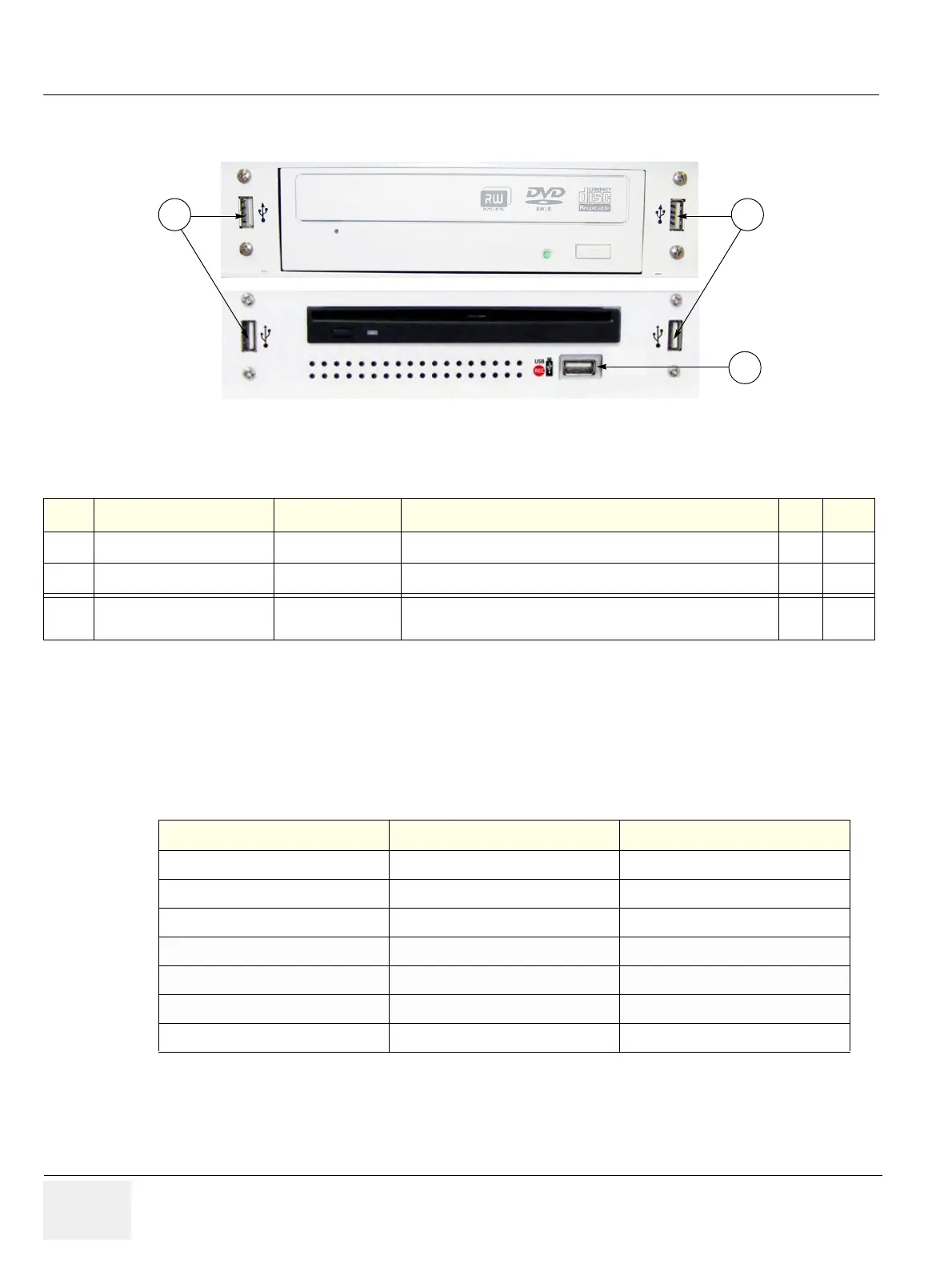
3-8-4-1 External I/O Pin Outs
Figure 3-56 External I/O Connectors - next to DVD- or DVR Drive
Table 3-10 External I/O Connector - Description
Item Connector Name Table Number Description
1
USB*
Table 3-13 USB-2.0 port
2
USB*
Table 3-13 USB-2.0 port
3
USB REC (DVR only)
BT12/BT13 only:
dedicated USB port on optional DVR (record to USB-stick)
Table 3-11 VGA OUT Connector, Sub-D 15 Pin
Pin No Output Signal Description
1 VGA OUT1 R Red
2 VGA OUT1 G Green
3VGA OUT1 BBlue
4, 9,11,12,15 N/C N/C
5, 6, 7, 8, 10 GND GND
13 VGA OUT1 HS H Sync
14 VGA OUT1 VS V Sync