GE HEALTHCAREDRAFT VOLUSON E8 / VOLUSON E6
D
IRECTION KTD102576, REVISION 7 DRAFT (AUGUST 23, 2012) SERVICE MANUAL
Chapter 3 - Setup Instructions 3-55
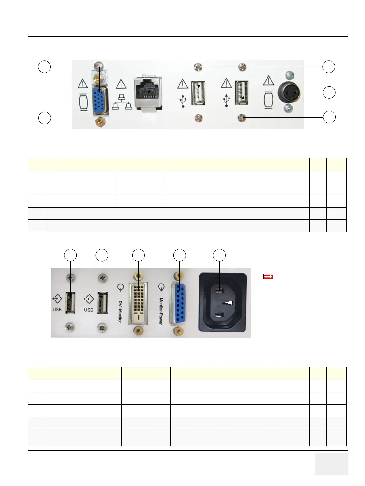
3-8-4 External I/O Connectors
Figure 3-54 External I/O Connectors - on Rear of System
Table 3-8 External I/O Connector - Description
Item Connector Name Table Number Description
1
VGA OUT
Table 3-11 Connector for external Monitor
2
NETWORK
Table 3-12 DICOM input/output, twisted pair RJ-45 10/100 megabit/s
3
USB
Table 3-13 USB-2.0 port
4
USB
Table 3-13 USB-2.0 port
5
S-Video OUT
Table 3-14 S-Video Out Connector
Figure 3-55 External I/O Connectors - on Back of Console
Table 3-9 External I/O Connector - Description
Item Connector Name Table Number Description
1
USB
Table 3-13 USB-2.0 port
2
USB
Table 3-13 USB-2.0 port
3
Monitor Pwr
Table 3-15 Monitor Power
4
DVI-D Out
Table 3-16 Monitor DVI-D (Digital Visual Interface)
5
AUX
main outlet for auxiliary devices
(not available at BT10/BT12/BT13 HW)
BT-Version:
The main outlet for auxiliary
devices is not available at
systems with BT10/BT12/BT13
hardware version
(or, if the main
harness has been replaced).