GE HEALTHCARERAFT VOLUSON E8 / VOLUSON E6
D
IRECTION KTD102576, REVISION 7 DRAFT (AUGUST 23, 2012) SERVICE MANUAL
5-10 Section 5-2 - General Information
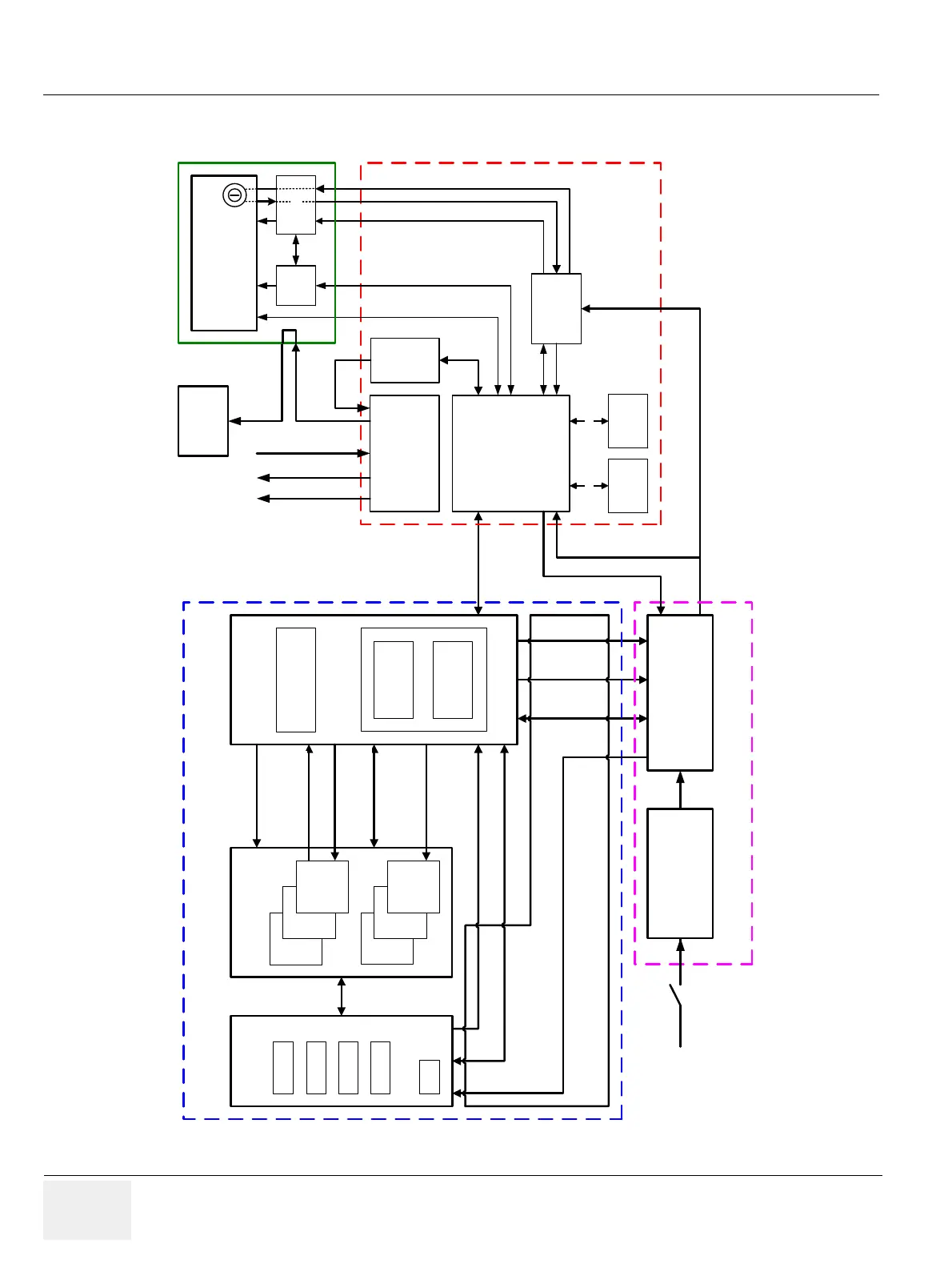
5-2-2 Block diagram Voluson E8 / Voluson E6
Figure 5-4 Voluson E8 / Voluson E6 - Block diagram
RFI
RF-Interface
RSR
RST
RTM Rx/Tx
Motherboard
RTP Secondary
Power Supply
Console
(User Interface)
PC
Motherboard
RTV - Video Management
(Legacy Analog Video I/O
and digital VCR, MPEG-2)
ADD2- Card
or
Graphic - Card
HDD
Optional
Device
Serial ATA
Probe / Code Select, serial 10 Mb/s
Hall, Probe Code
1
, ...
RTK Mainboard
PCI 32 Bit
33 MHz,
132 MB/s
PCI-Expr.
RTB
Distribution
Board
RTN Primary
Power Supply
Monitor
Serial ATA
RTH
RTT
DVI-out
RTF
ProbeConnect
FPGA
RSR
RSR
RST
RST
BF Rx Data, LVDS, 14 pairs
50MHz Clock
Rx coeff. LVDS, 8 pairs
600Mb/s
BF Config (CW Gain, Test, ...)
Serial 10 Mb/s
Tx coeff. LVDS, 8 pairs,
600 Mb/s
FPGA Config. Serial 50MHz
I²C Bus
Serial I/F to Motor
Power Drivve
CPP Analog I/O
Analog VGA Out
Composite / S-Video Out
Composite / S-Video In
DVI-cable
BackEnd
FrontEnd
Power Distribution
DSP Motor control
(Digital Signal Processor)
Interface
Processing
ON/OFF
5V STB (Standby)
5V STB (Standby)
5V STB (Standby)
PS_0N (0..on, 1..off)
Mains
Power
ON/OFF
ON/OFF
USB Hub Top
USB UI
Voltage Supply: +3,3V, -3,3V, 2,0V, TxPower 1, TxPower 2
FPGA