GE HEALTHCAREDRAFT VOLUSON E8 / VOLUSON E6
D
IRECTION KTD102576, REVISION 7 DRAFT (AUGUST 23, 2012) SERVICE MANUAL
Chapter 8 - Replacement Procedures 8-27
8-17-3-1 Installation Procedure at systems WITH power connector (cont’d)
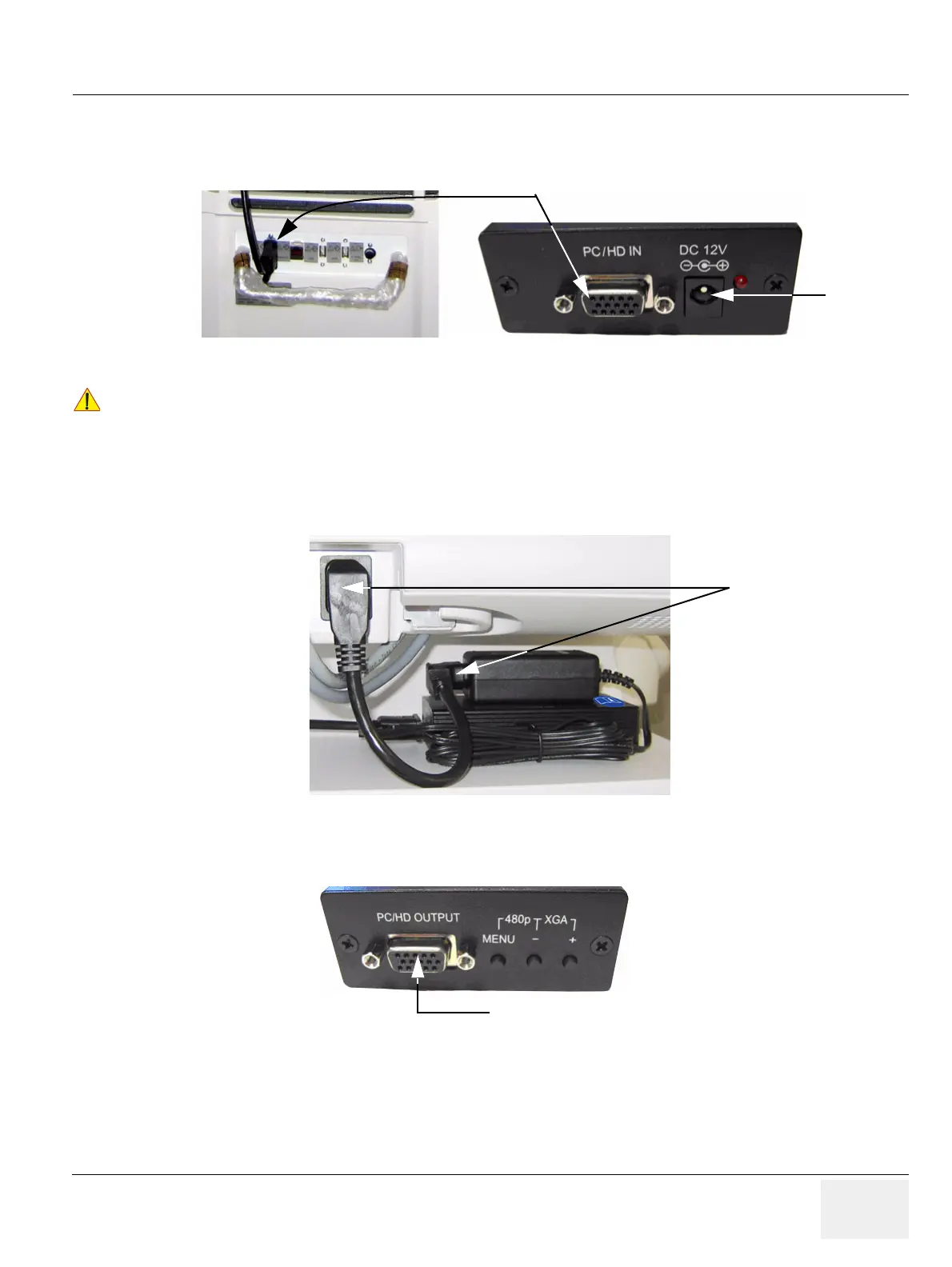
4.) Connect the RGB Video Cable from the VGA Out Connector (on Voluson E8 / Voluson E6 system)
to the PC/HD IN Connector on the Image Resizer Box (see: Figure 8-29 below).
5.) Connect the DC-Power Output from the Power Supply to the DC-Power Input at the Image Resizer
Box (see: Figure 8-29 above).
6.) Plug the Power Cable into the Power outlet above this shelf and plug the other end into the Power
Supply’s input socket (see: Figure 8-30 below).
7.) Connect your Secondary Monitor to the Image Resizer Box at its PC/HD OUTPUT Connector.
8.) After the installation, Power ON/Boot up the system as described in Section 3-6-2 on page 3-31.
9.) Adjust the VGA Image Resizer settings as described in Section 3-5-7-1 on page 3-24.
10.)Measure leakage currents according to IEC 60601-1 respectively UL 60601-1.
Figure 8-29 VGA Video Connection
!! NOTICE:
Place the cable in a way, that it can not get damaged when moving the System or when the height of
the User Interface gets adjusted.
Figure 8-30 Power Connection
Figure 8-31 Connector for Secondary Monitor
VGA Video Connection
DC-Power
Input
Connector for Secondary Monitor