—————— TPD32-EV ——————
420
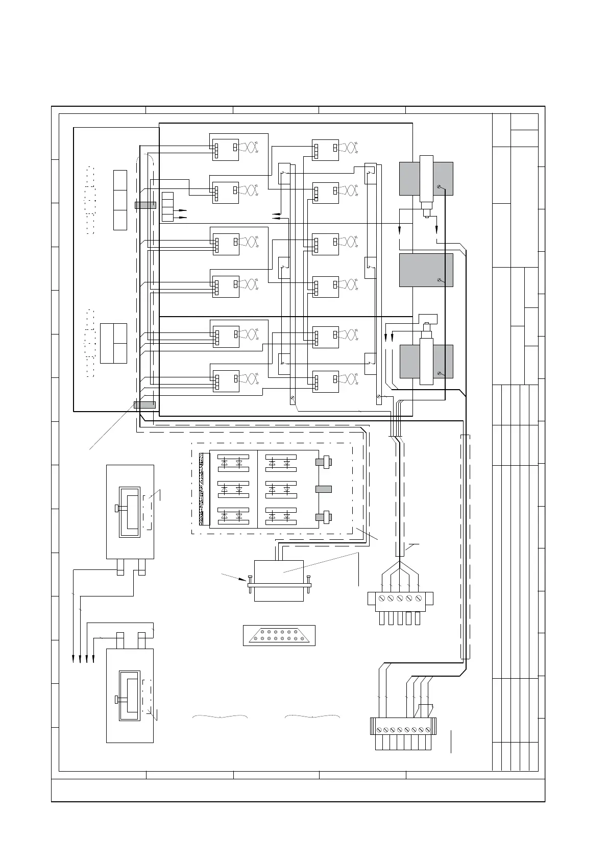
9.4 CONNECTION OF EXTERNAL POWER BRIDGES
Figure 9.4.1: ESE5855 TPD32-EV-....-1010....3300-4B-E
Posiz.TARGA
Position of rating plate
-Connett.vista lato saldatura.
-Custodia aperta
7-8 MN-bianco
1 IT1-rosso
2 IT2-blu
3 IT3-nero
4 IT4-rosso
5 IT5-blu
6 IT6-nero
13-12 MP-marrone
-Connector solder side view
( Cover removed )
7-8 MN-white
1 IT1-red
2 IT2-blue
3 IT3-black
4 IT4-red
5 IT5-blue
6 IT6-black
13-12 MP-brown
Rev. Date
Modification Description
Des/Sch
Appvd
Des. Sch.
Appr.
Nr:
Rev.
Page
over
Date:Name:
Non è permesso consegnare a terzi o riprodurre questo documento nè, utilizzare il contenuto o renderlo
comunque noto a terzi senza la nostra autorizzazione esplicita. Ogni infrazione comporta il risarcimento dei danni subiti.
E' fatta riserva di tutti i diritti derivati da brevetti o modelli.
All rights are reserved in the event of the grant of a patent or the registration of a utility model or design.
is forbidden without express authority. Offenders are liable to the payment of damages.
Copyng of this document, and giving it to others and the use or communication of the contents thereof,
Loc. Funct.
1
10
11
12
13
14
15
4
5
6
7
8
9
2
1
3
2 3 4 5 6 7 8 9
10 11 12 13 14 15
A
BCDE
1
28/05/12
ESE5855
BFE
EC
EC
TPD32-EV-...-1010...3300-4B-E
A
01
00
PE
31 32
PE
V3
U3
F3
CT-U
CT-W
+ +
+
+
+ +
U
V
W
8
.
.
.
.
.
2
1
15
14
9
.
.
.
U
V
W
W
U
K
K
-KPT11-
Custodia
Cover
6S8V99
K
K
1
2
3
4
5
6
7
8
U
V
W
C
D
-KP-
-KPT31-
Viti fissaggio
Fastening screws
8S8L69
CT-W
CT-U
Sez.min. AWG 22
MONTAGGIO E COLLEGAM.TA
Vista dal basso -Attenzione alla posiz.morsetto K
CT Mounting and wiring (Notice position of terminal K)
-Bottom view
Fissare i cavi inguainati
sulla cappa di ventilaz.
Tighten sheathed cables
onto the Fan hood
Morsett.Ventilat.
Fan terminals
TAS2(...3)
Remark:
twist wires
black
black
black
red
blue
black
orange
red
brown
blue
brown
7
8
7
8
5
6
TAS2(...3)
Posiz.TARGA
Position of rating plate
(to KPT31)
red
brown
brown
blue
brown
1
2 3
wires cross section 1mm /AWG18
free length 1,3 m,sheated
2
6
5
Disposiz.PONTE
BRIGDE layout
Guaina diam.8-Lungh.libera m 1,2
Sheath diam.8 mm-Free length 1,2 m
wires cross section 2,5 mm /AWG14
free length 1,3 m,sheated
Attenzione:Ponte di potenza predisposto per l'estrazione frontale di ogni singola
fase (U-V-W)-Collegare in modo tale da facilit.al max.l'estrazione.
Warning:Power bridge is designed for front extraction of individual phase
modules (U-V-W).Arrange wiring,cable or bar connections to keep extraction area clear
2
blue
D (C)
C (D)
61
62
F2F1
F4 F5
F6
4
5
6
6°
5°
4°
1°
2° 3°
red
Termostati
Thermostats
{
Min.cross section AWG 22
61
62
81
82
IT1
MP
IT4
MN
IT2
MP
MN
IT3
MP
IT6
MN
IT5
Schema topografico collegamento ponte
Topographical scheme bridge wiring
T
P
G
K
T1
T1
T
P
T
P
G
K
T1°
T1°
T
P
T
P
G
K
T2
T2
T
P
T
P
G
K
T2°
T2°
T
P
T
P
G
K
T3
T3
T
P
T
P
G
K
T3°
T3°
T
P
T
P
G
K
T6°
T6°
T
P
T
P
G
K
T6
T6
T
P
T
P
G
K
T5°
T5°
T
P
T
P
G
K
T5
T5
T
P
T
P
G
K
T4°
T4°
T
P
T
P
G
K
T4
T4
T
P
Fus.
Fuses
MN
MP

 Loading...


