—————— Instruction manual ——————
483
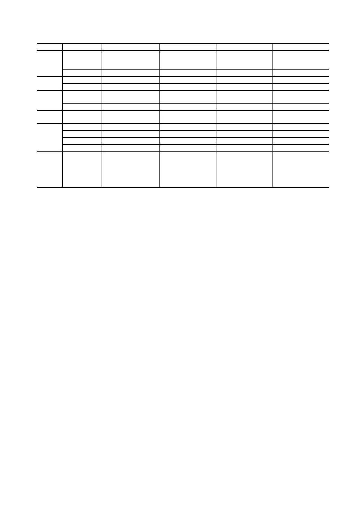
Electrical data for all of the terminals and connectors listed
Connector Terminal Function IN/OUT Voltage Current
-
U1, V1
Motor field circuit AC power
input
IN 1 x 230 …460A
ac, 50/60Hz 40 / 70Aac
C1, D1 Motor field DC power output OUT 0 …360Vdc 40 / 70adc
KP
U, V, W Mains voltage feedback IN 3 x 230 …690A
ac, 50/60Hz 200mA
C, D Armature voltage feedback IN 0 …810
Vdc 10mA
KPT31
1, 2, 3
Connection of bimetal
thermostats
IN ----- 4mA
5, 6, 7, 8 CT connection IN ----- 0 …5A
ac
KPT11,
KPT21
15 poli Sub-D
Pulse transformer primary
winding side circuits
OUT ----- 1A peak
XM
U2, V2 Regulation power supply IN 1 x 115/230A
ac, 50/60Hz 1/0,5Aac
35, 36 Contact OK Relay OUT 250A
ac max 1A AC11
75, 76 Relay 2 contact OUT 250A
ac max 1A AC11
78, 79 Motor thermistor IN ----- -----
XCT 0VI, 0VI, RCT, RCT
Connection of external CT
burden resistor with second-
ary current of >1 Aac
(see "A1.6.3 Configuration of
the armature current feed-
back circuit" on page 483)
OUT ----- 5A max
Dissipated power
See"Table2.5.2:DissipatedpowerTPD32-EV-CUseries"onpage57.
Regulation and control section
Generalinformationisprovidedinchapter"4.4RegulationSection"onpage69.
R-TPD32regulationcard:
• Dip-switchS15,see"Table4.4.2-B:Dip-switchS15AdjustmentoftheTPD32-EV-CU-...seriesmainsvolt-
ageregulationcard"onpage71.
• Dip-switchS14,see"Table2.3.3.4-F:FieldcurrentresistorsSizesTPD32-EV-CU-..."onpage32.
A1.6.3 Configuration of the armature current feedback circuit
Overview
Thecurrentfeedbacksignalissenttothecontrolunitbytwocurrenttransducers(CT)insertedonphasesUand
Wofthecontrolledpowerbridge.ItisrectiedontheFIRXP-XXcardbyathree-phasediodebridgeandap-
pliedtoaburdenresistorthatconvertsitintoavoltagesignalproportionaltotheDCmotorcurrentvalue.This
isthenappliedtothearmaturecurrentregulatorwhichcomparesitwiththereferencevalue.
ThestandardFIRXP-XXcardoffersachoiceoftwoburdenresistor(RB)values,2.5Ohmor5Ohm,which
aresuitableinthemajorityofcases.Otherwiseanexternalburdenresistorcanbeused,connectedbetween
terminalsRCTand0VI.
Inordertoenablepreciseadjustmenttothemanypossibleratedcurrentvalues(sizeofthecontrolledpower
bridge),aprogrammablegainamplier(N8)isinsertedbetweentheburdenresistorandthecurrentregulator.
Thegainissetbymeansofa12-bitbinarynumberselectedwithdip-switchesS3andS4.

 Loading...