—————— Instruction manual ——————
81
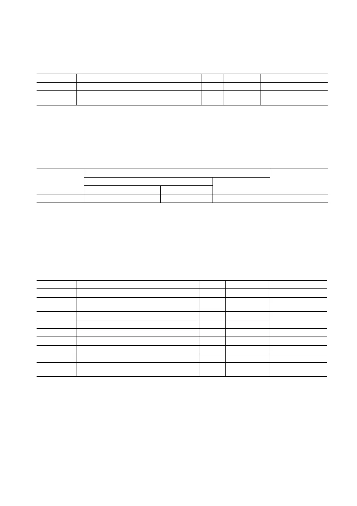
4.7.2 DEII Terminal Assignment
Table 4.7.2.1: Terminal assignment (Terminals 0Venc and +Venc)
Designation Function I/O max volt. max curr.
0Venc 0 V supply to the encoder I - -
+Venc
+15 ... 24 V supply to the encoder (S1, S2, S3 open) +5V sup-
ply to the encoder (S1, S2, S3 closed)
I +24V depending on encoder data
I=InputO=Output
Table 4.7.2.2: Permissible cable cross section on the terminals of option card DEII
Terminals
Max cable connection section
Tightening
torque
[Nm]
[mm
2
]
AWG
flexible multi-core
0 Venc and +Venc 0.14 ... 1.5 0.14 ... 1.5 28 ... 14 0.5
Theuseofa3x0.1x0.02inches(75x2.5x0.4mm)atscrewdriverisrecommended.Striptheendsofthe
cablestoalengthof0.26inch(6.5mm).Onlyoneunpreparedwire(withoutferrite)shouldbeconnectedto
eachterminal.
Table 4.7.2.3: XS1 9-pole connector
Designation Function I/O max volt. max curr.
PIN 1 Channel B- I +24V 10.9mA
PIN 2 Supply voltage for the encoder (the allowed level depends on the
jumper position, see chapter 4.7.1
O +24V depending on ext. power
supply unit
PIN 3 Channel C+ (zero pulse) O +24V 10.9mA
PIN 4 Channel C- (zero pulse) I +24V 10.9mA
PIN 5 Channel A+ I +24V 10.9mA
PIN 6 Channel A- I +24V 10.9mA
PIN 7 Reference point for supply voltage O - -
PIN 8 Channel B+ I +24V 10.9mA
PIN 9 + 5V (only if S1-S2-S3 = TTL) O +5V depending on ext. power
supply unit
I=InputO=Output