46
INSTALLATION
June 1999
96-8000
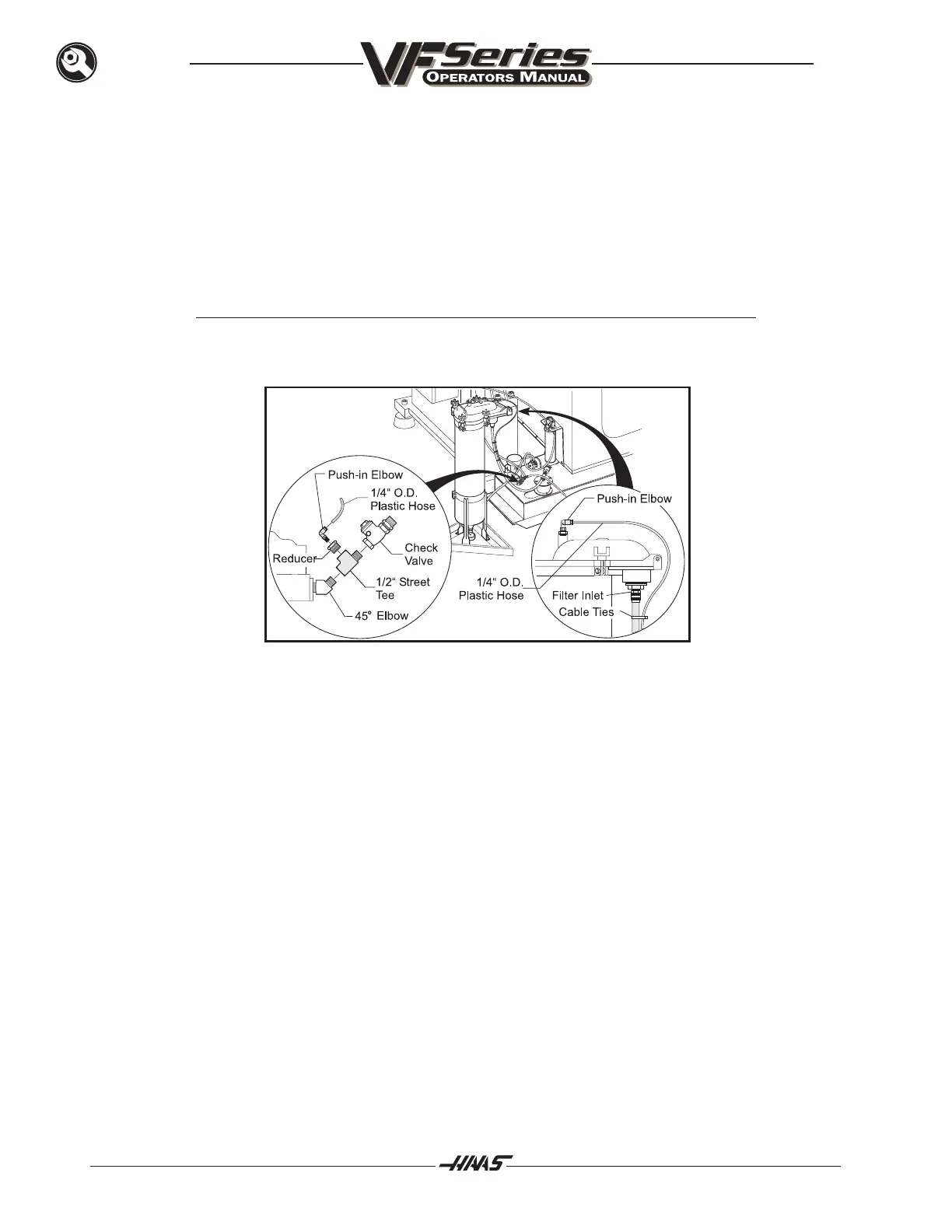
4. For large vertical machines, remove the original hose from the intake filter and replace with the
longer hose included in the kit. Secure it to the hose barb using the supplied hose clamp. The
hose may be trimmed shorter if desired for appearance. Attach the hose from the intake filter to the
inlet of the auxiliary filter.
5. Disconnect the 1/2 check valve from the 45
0
elbow at the base of the normal coolant pump. Install
the 1/2 street-tee from the kit between the 45
0
elbow and the check valve. Install the pipe reducer
from the kit into the side outlet of the street-tee. Install the 1/4" push-in elbow into the pipe re-
ducer. (See figure 3.0).
Note: The cap of the check valve should point upward for the check valve to function
properly.
Figure 3.0 Auxiliary Filter Priming System
6. Insert the 1/4" OD plastic hose into the push-in elbow on the pump. Route the hose along the
intake filter hose and around the hinge of the auxiliary filter. Trim the plastic hose to length and
insert it into the push-in elbow at the top of the filter. Secure the plastic hose to the inlet hose with
the supplied cable ties. (See figure 3.0).
7. Attach the hose from the bottom of the auxiliary filter to the inlet of the TSC gear pump.
8. Check that the filter lid is securely closed. Using a wrench handle or metal bar, tighten the two rear
bar nuts first and then the front pair. Torque the bar nuts according to the manufacturer's recom-
mendations. (approximately 30-50 ft-lbs)

 Loading...


