76 96-8000
June 1999
OPERATION
3.2 THE COORDINATE SYSTEM
The first diagram we are concerned with is called a NUMBER
LINE. This number line has a reference point zero that is called
ABSOLUTE ZERO and may be placed at any point along the line.
Fig. 3-1 Horizontal number line.
The number line also has numbered increments on either side of absolute zero. Moving away from zero to the
right are positive increments. Moving away from zero to the left are negative increments. The +, or positive
increments, are understood, therefore no sign is needed.
We use positive and negative along with the increments value to indicate its relationship to zero on
the line. In the case of the previous line, if we choose to move to the third increment on the minus (-)
side of zero, we would call for -3. If we choose the second increment in the plus range, we would call
for 2. Our concern is with distance and direction from zero.
Remember that zero may be placed at any point along the line, and that once placed, one side of zero
has negative increments and the other side has positive increments.
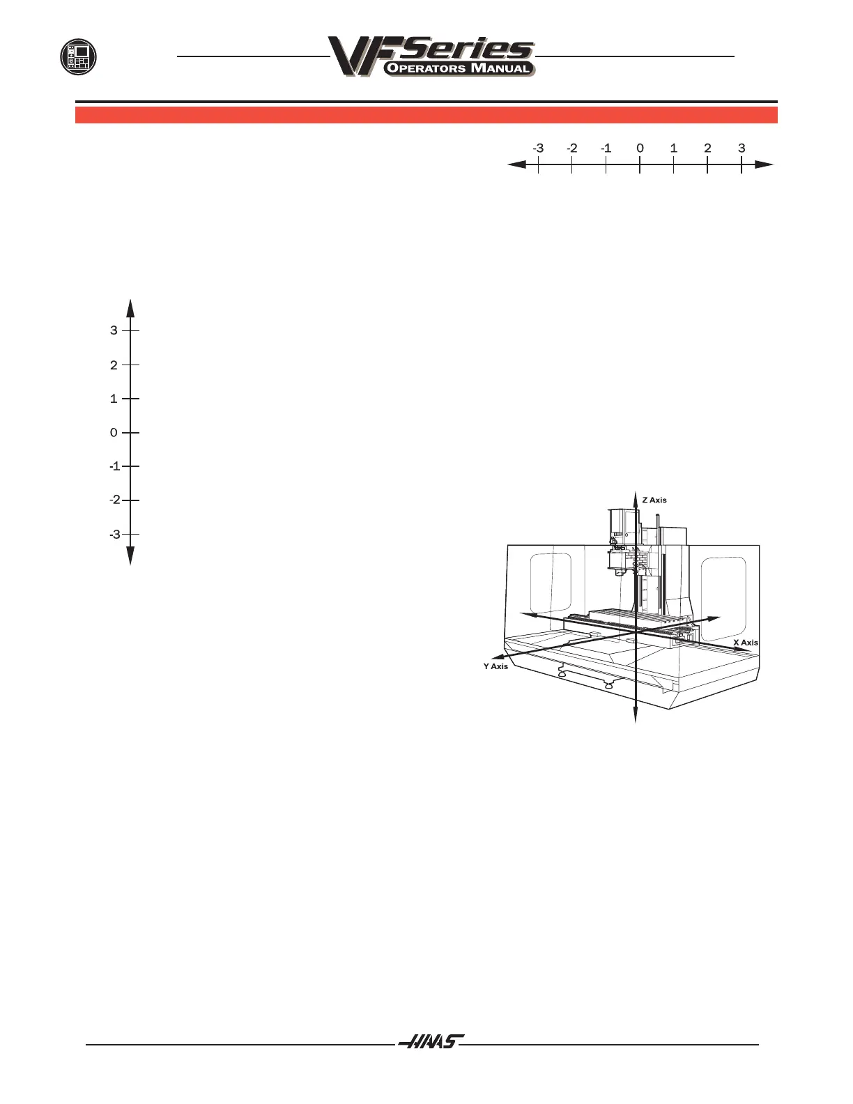
The next illustration (Fig. 3-3) shows the three directions of travel on a vertical machining center. To
carry the number line idea a little further, imagine
such a line placed along each axis of the machine.
Fig. 3-2
The first number line is easy to conceive as belonging to the
left-to-right, or X, axis of the machine. If we place a similar
number line along the front-to-back, or Y, axis, the incre-
ments toward the operator are the negative increments, and
the increments on the other side of zero away from the
operator are the positive increments.
Fig. 3-3 VF-1 showing X, Y, and Z axis lines.
The final axis of travel on our machine is the up-and-down, or Z, axis. When we place a number line on the Z
travel, the positive increments are up above zero and the negative values are down below zero. Actu-
ally, the increments on each number line on the HAAS machining centers equals .0001 inches. Also, while a
line theoretically travels infinitely in either direction once established, the three lines placed along the X, Y, and
Z axes of the machine do not have unlimited accessibility. That is to say, we are limited by the range of travel on
the machine.
Remember, when we are moving the machine, we are concerned with positioning the spindle. Although the
machine table is the moving part, we have to keep in mind our coordinates are based off our theoretical spindle
movement.

 Loading...


