EasyManuals Logo

Haas VF Series Operator's Manual

Haas VF Series
564 pages
To Next Page IconTo Next Page
To Previous Page IconTo Previous Page
Page #42 background imageLoading...
Page #42 background image
42
INSTALLATION
June 1999
96-8000
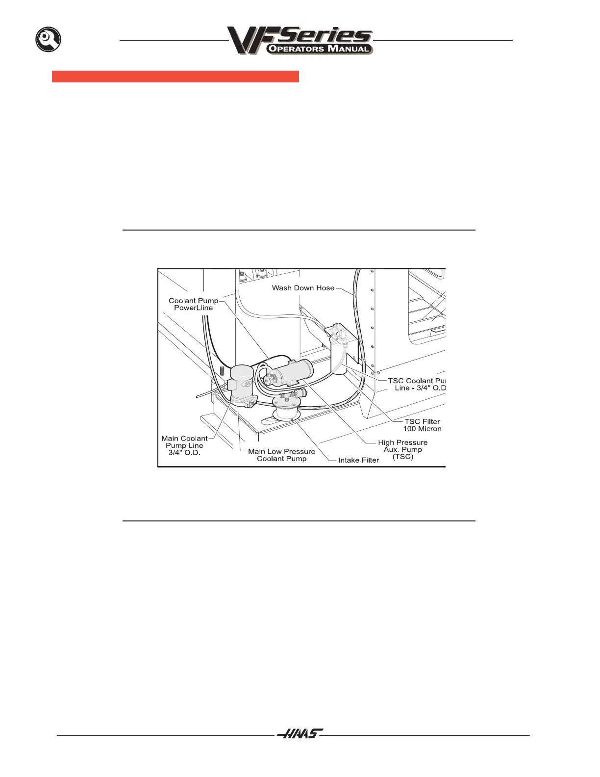
COOLANT T ANK I NSTALLATION
1. Position the coolant tank under the left side of the machine as shown.
2. Connect the main coolant line (3/4" O.D.) to the main pump.
3. Connect the main pump power line to the outlet on the right side of the electrical panel.
4. If machine includes Through the Spindle Coolant option, attach the 3/4" O.D. coolant line to the
TSC pump.
NOTE: The TSC power line is hard wired to the main pump power line.
5. Fill coolant tank with coolant (approximately 40 gallons). VF-6 through 10 (approx. 80 gallons)
NOTE: Before operating the coolant system, ensure the drain is positioned half way
over tank strainer.
6. Route the coolant return hose as shown.

Table of Contents

Other manuals for Haas VF Series

Questions and Answers:

Question and Answer IconNeed help?

Do you have a question about the Haas VF Series and is the answer not in the manual?

Haas VF Series Specifications

General IconGeneral
Machine TypeVertical Machining Center
ControlHaas CNC Control
Z-Axis Travel20-30 inches (varies by model)
Y-Axis Travel16 - 30 inches (varies by model)
Spindle Motor20-30 hp (depending on model)
Tool Capacity20-40 tools (varies by model)

Related product manuals