45
INSTALLATION
June 1999
96-8000
OPTIONAL A UXILIARY F ILTER FOR TSCHP SYSTEM
APPLICATION
This Auxiliary Filter is used to protect the high pressure TSC pump from particle damage. It is recommended
for customers doing medium to high production machining of cast aluminum, cast iron or titanium. It may also
be useful for customers who perform high speed milling operations and produce small powder-like chips.
The filter unit consists of a #2 filter bag, filter housing, pipe fittings and hoses. The large size of the filter bag
will extend the time interval between bag changes. To reduce wear and prolong the filter system, a small plastic
hose is connected between the filter housing and the primary coolant pump to prime the system with coolant.
The filter is automatically topped off whenever P-Cool is used. The amount of flow through the priming hose has
an unnoticeable effect on normal coolant operation.
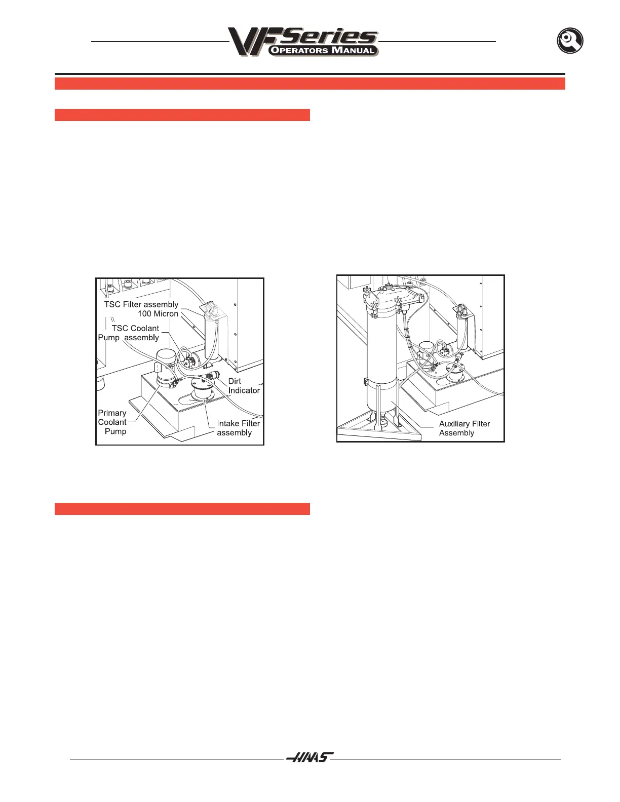
Figure 1.0 Stock Filtration Setup Figure 2.0 Filtration Retrofit
INSTALLATION
1. Place the filter assembly approximately six inches behind the coolant tank, for tanks that pull out
from the side or for Horizontal machines. For large vertical machines, place the filter one foot
behind the enclosure with the inlet turned to the left so the hinged lid does not strike the enclosure
when it is opened for filter changes. For tanks that pull out from the rear of the machine, place the
Auxiliary Filter beside the coolant tank next to the enclosure.
2. Secure the filter unit to the floor using 1/4 concrete anchors. (not provided)
3. Using a pipe wrench, turn the tee on top of the intake filter clockwise 1/8 turn so the hose is
between the wing nuts. Remove the wing nuts from the filter and pull off the cover. Remove the filter
element and re-install the cover with the hose pointing out toward the edge of the coolant tank.

 Loading...


