TECHNICAL REFERENCE
467
June 1999
96-8000
12.15 SPARE USER M CODE I NTERFACE
The M code interface uses outputs M21-23 and one discrete input circuit. M codes M21 through M23 will
activate relays labelled M21-23. These relay contacts are isolated from all other circuits and may switch up to
120V AC at one amp. The relays are SPDT. WARNING! Power circuits and inductive loads must have snubber
protection.
Note: If the optional M code relay board is installed, relays M21-28 become available
on the secondary board. These relays will be controlled by outputs M21-28.
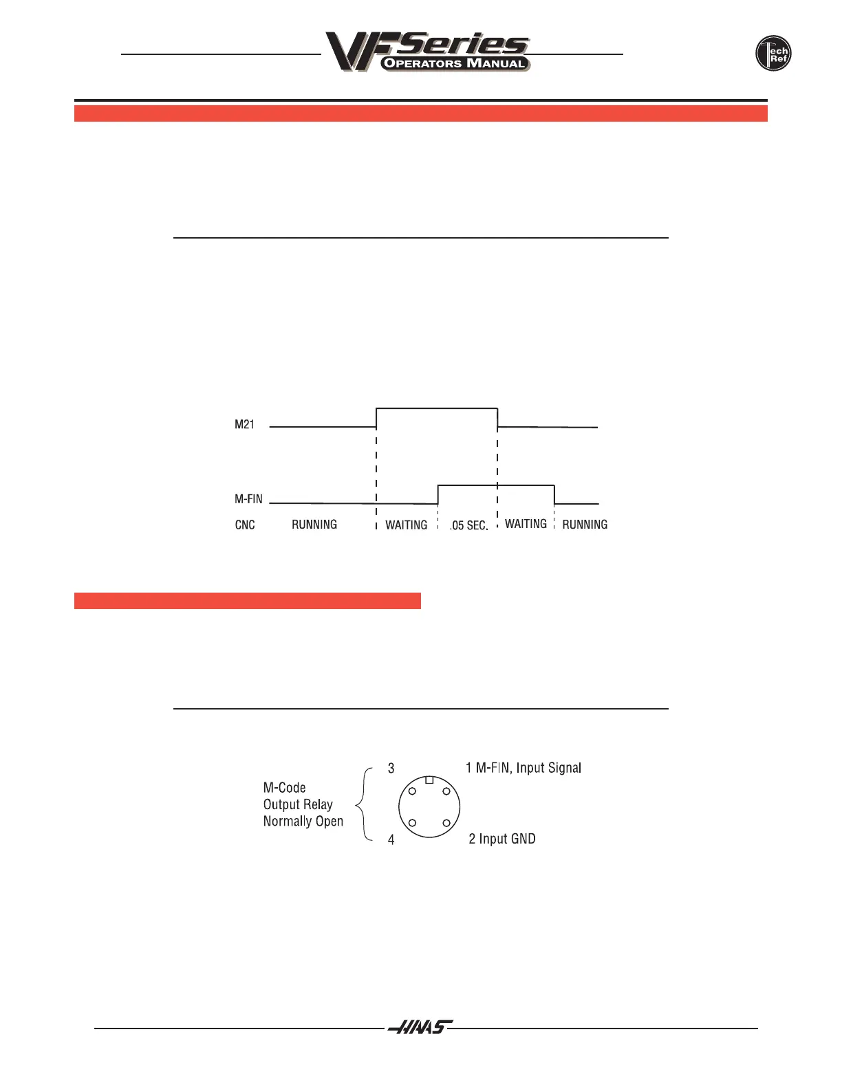
The M-FIN circuit is a normally open circuit that is made active by bringing it to ground. The one M-FIN applies
to all eight of the user M codes.
The timing of a user M function must begin with all circuits inactive, that is, all circuits open. The timing is as
follows:
The Diagnostic Data display page may be used to observe the state of these signals.
M FUNCTION R ELAYS
The IOPCB contains three relays (M21-M23) and the optional M code relay board contains eight (M21-M28),
either one of these groups of relays may be available to the user. M21 is already wired out to P12 at the side of
the control cabinet. This is a four-pin DIN connector and includes the M-FIN signal.
Note: If the optional M code relay board is installed, the relays on the IOPCB are to
be left unused.

 Loading...


