58
INSTALLATION
June 1999
96-8000
4. Remove the leveling screws at the four corners of the base. Insert the 3/4-10 mounting bolts
through the leveling screw holes. Tighten the bolts to the coupler mounted in the pallet.
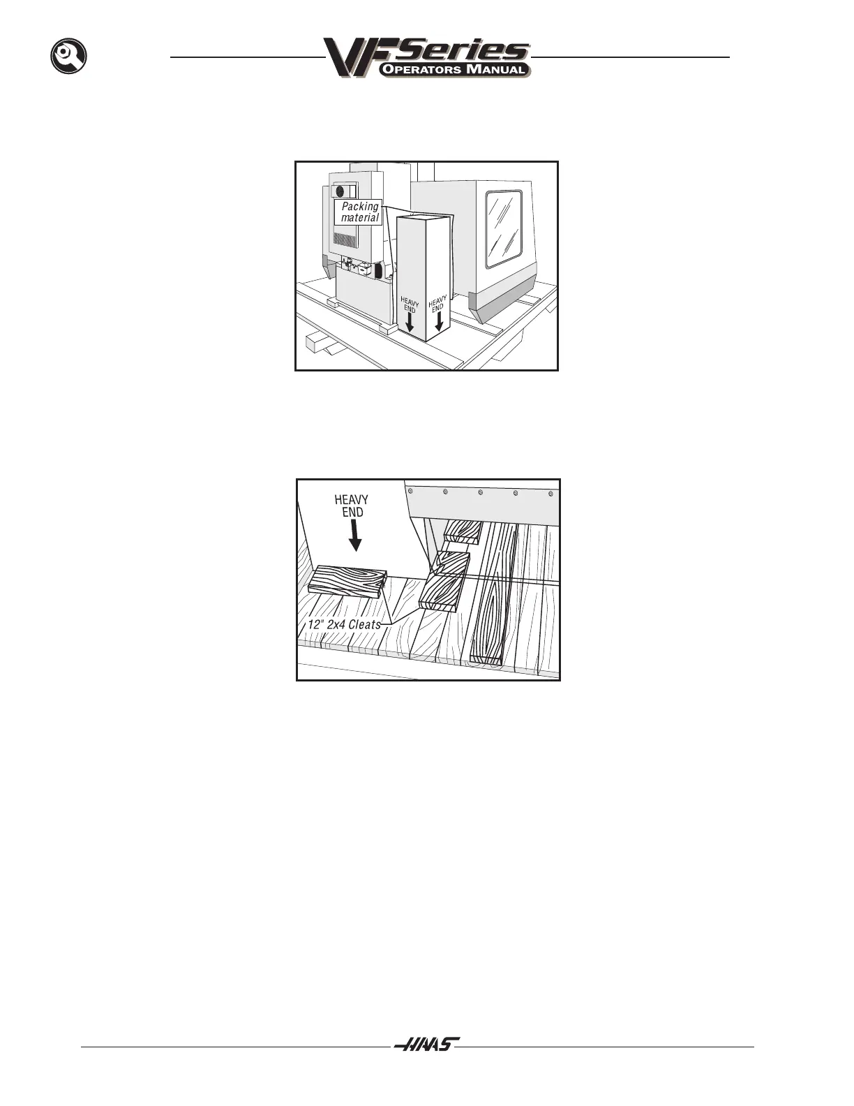
5. Drain and clean the coolant system. Pack it in the box it came in and slip the box, heavy end
down, into the space on the left side of the machine between the panel, at the back of the ma-
chine, and the enclosure.
WARNING!
THE BOX MUST BE POSITIONED WITH THE HEAVY END DOWN. THEN SLIP
PACKING MATERIAL BETWEEN THE BOX AND THE MACHINE AT ALL POINTS
WHERE THERE IS CONTACT. AND FINALLY, NAIL A 12", TWO-BY-FOUR CLEAT
TO THE PALLET WITH 16D NAILS TO HOLD THE BOX IN PLACE.
6. Put the leveling screws, pads, allen wrench, and screwdriver in the tote kit and position it between
the coolant box and the support strip toward the front of the machine. Then nail a 12", two-by-four
cleat to the pallet with 16d nails to hold the tote kit in place.
7. Clean the drip pan as necessary and slide it under the machine. If the machine is furnished with
the drain bucket, place it at the rear of the machine, under the air/lube panel, and tie into place.

 Loading...


