107Connection
HBMQuantumX
6.9.1 MX1601pin assignment
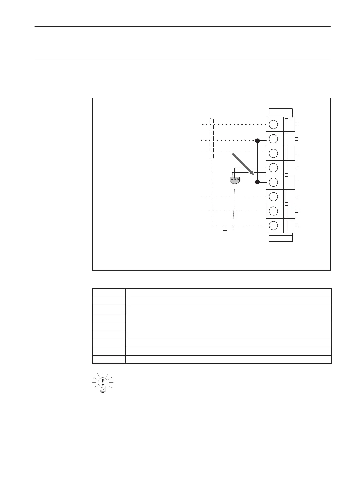
So that insertion or removal of a transducer connection can be unmistakably identified, Pin 2
and Pin 5 in the connector plug must be bridged! If this bridge is missing, no measurement
values will be recorded at the connection!
1
2
3
1
2
3
4
5
6
7
8
1-Wire-EEPROM
(Maxim DS2433+)
Bottom view
2 Data
3 no function
1
Bridge
Fig.6.13: Pin assignment of the connector plug, view from the connection side
Pin Connection
1 Voltage input 10 V (+), 100 mV (+), IEPE (+)
2 Signal ground, TEDS (−)
3 Current input 20 mA (+)
4 TEDS (+)
5 Always connect with Pin 2! (Plug identification)
6 Active sensor supply (+)
7 Active sensor supply (−)
8 Housing (shield connection)
NOTE
The transducer excitation voltage can be set in the range of 5 ... 24 V and is only
available at channels 1 ... 8. At channels 9 ... 16, the supply voltage (10 V ... 30 V) is
output less approx. 1 V. A current drain of max. 30 mA is possible; the current limiter
cuts the transducer excitation voltage at a higher current drain.