93Connection
HBMQuantumX
6.5.1 MX410 pin assignment
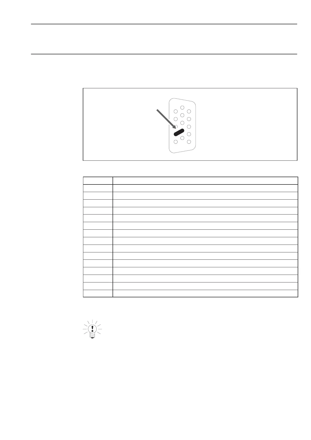
So that insertion or removal of a transducer connection can be unmistakably identified, Pin 4
and Pin 9 in the connector plug must be bridged! If this bridge is missing, no measurement
values will be recorded at the connection!
1
4
5
6
9
11
15
Bridge
Fig.6.7: Pin arrangement of connection plug, view from the solder side
Pin Connection
1 TEDS (+)
2 Bridge Excitation voltagen (−)
3 Bridge Excitation voltage (+)
4 Always connect with Pin 9! (Plug identification)
5 Measurement signal (+)
6 TEDS (−)
7 Sense lead (−)
8 Sense lead (+)
9 Signal ground
10 Measurement signal (−)
11 Active sensor supply (−)
12 Active sensor supply (+)
13 Current input "30 mA (+)
14 Voltage input 10 V, IEPE (+)
15 Reset external charge amplifier
The analog output can be tapped via BNC. Please see chapter 7 ”Functions and outputs” for
information about the configuration.
NOTE
Many HBM transducers are fitted with 15-pin D-SUB connectors (2 rows). The adapter
cable 1-KAB416 can be used for connection to the 3 row D-SUB-15HD device
connectors of the MX840. Pins 4 and 9 are already bridged in this adapter cable.