16
Introduction
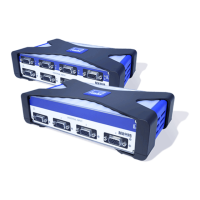
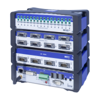
HBM QuantumX
2.3 Channel overview
M
X
1
609
²
)
M
X
4
71
M
X
8
79
M
X
8
78
MX8
4
0A
QuantumX Modules
MX4
4
0A
C
X27
MX160
1
MX161
5
M
X
4
10
M
X
4
60
•
M
X
1
609
²
)
16
300
14
•
M
X
4
71
-
-
-
•
•
•
M
X
8
79
-
-
-
•
•
M
X
8
78
-
-
-
•
Thermocouples
••
•
•
•
Number of channels (total)
Data rate (Samples/s)
Bandwidth (Hz)
Quarter-bridge strain gages
Half-bridge strain gages
Full-bridge strain gages
8
19200
3200
Digital OUT (static)
Digital IN (static)
Mathematics
Analog outputs
CANbus
Torque / rotary speed
PWM
Frequency measurement, pulse counti
SSI
Incremental encoder
Indctive rotary encoder
PT100 resistance thermometer
Potentiometers
Resistance
Piezoresistive transducer
Current fed piezoelectric transducer
(IEPE)
Current (± 20 mA)
Voltage
LVDT
Inductive half-bridge
Inductive full-bridge
•
••
•
•
•
• ³)
•
•
• ³)
•
MX8
4
0A
•
•
MX4
4
0A
4
19200
3200
•
•
•
•
•
•
• ¹)
•
¹) For connecting current-fed piezoelectric transducers, a Smart Module (1-EICP-B-2) is required.
•
•
•
•
•
•
• ¹)
•
•
•
•
•
•
•
•
C
X27
-
-
-
•
MX160
1
16
19200
3000
•
•
•
MX161
5
16
19200
3000
•
•
•
•
•
•
•
•
M
X
4
10
4
96000
38000
•
•
• ³)
•
•
•
•
•
•
M
X
4
60
4
96000
38000
•
•
•
•
³) Pluggable quarter bridge modules available, see Accessories SCM-SG120 and SCM-SG350.
²) MX1609 supports type K only; MX1609-T type T only.
See data sheets for precise technical specifications. The pin assignments can be found in the following chapters.