49Connection
HBMQuantumX
5 Connecting individual QuantumX modules
5.1 Connecting the supply voltage
Connect the modules to a DC voltage of 10 V ... 30 V (recommended 24 V), see the table for
the power consumption per device.
CAUTION
A rule of thumb for voltage distribution via FireWire says:
”An external supply voltage of equal potential
is required at every third module”.
Defects in the device cannot be excluded if a supply voltage > 30 V is used. If the supply
voltage drops below 10 V, the modules switch off.
In the event of battery operation in a vehicle, we recommend incorporating an uninterrupted
voltage supply between battery and module to compensate for voltage drops during starting
processes.
Module Typical power consumption, including transducer excitation (Watt)
MX840 13
MX840A 12
MX440A 10
MX1601 13
MX410 15
MX460 9
MX1609 6
MX1609-P 6
CX22 12
CX27 7
MX878 7
MX471 6
If several modules are connected to each other via FireWire for time−synchronous data
acquisition (see Fig.5.4), the supply voltage can be looped through. The power pack used
must be able to provide the appropriate output.
The maximum permissible current on the FireWire connection cable is 1.5 A.If the chain is
longer repeating the supply connection is mandatory.
If several amplifiers are operated non−synchronously (see Fig.5.3), they must be supplied
separately.
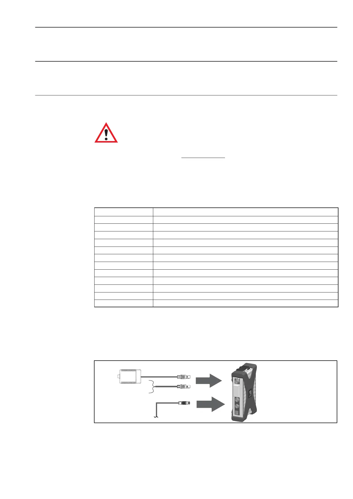
X104
NTX001
1−Kab271−3
or
X101/X102
1−Kab269
FireWire
Fig.5.1: Connecting socket for supply voltage