89Connection
HBMQuantumX
6.3.1 MX840A pin assignment
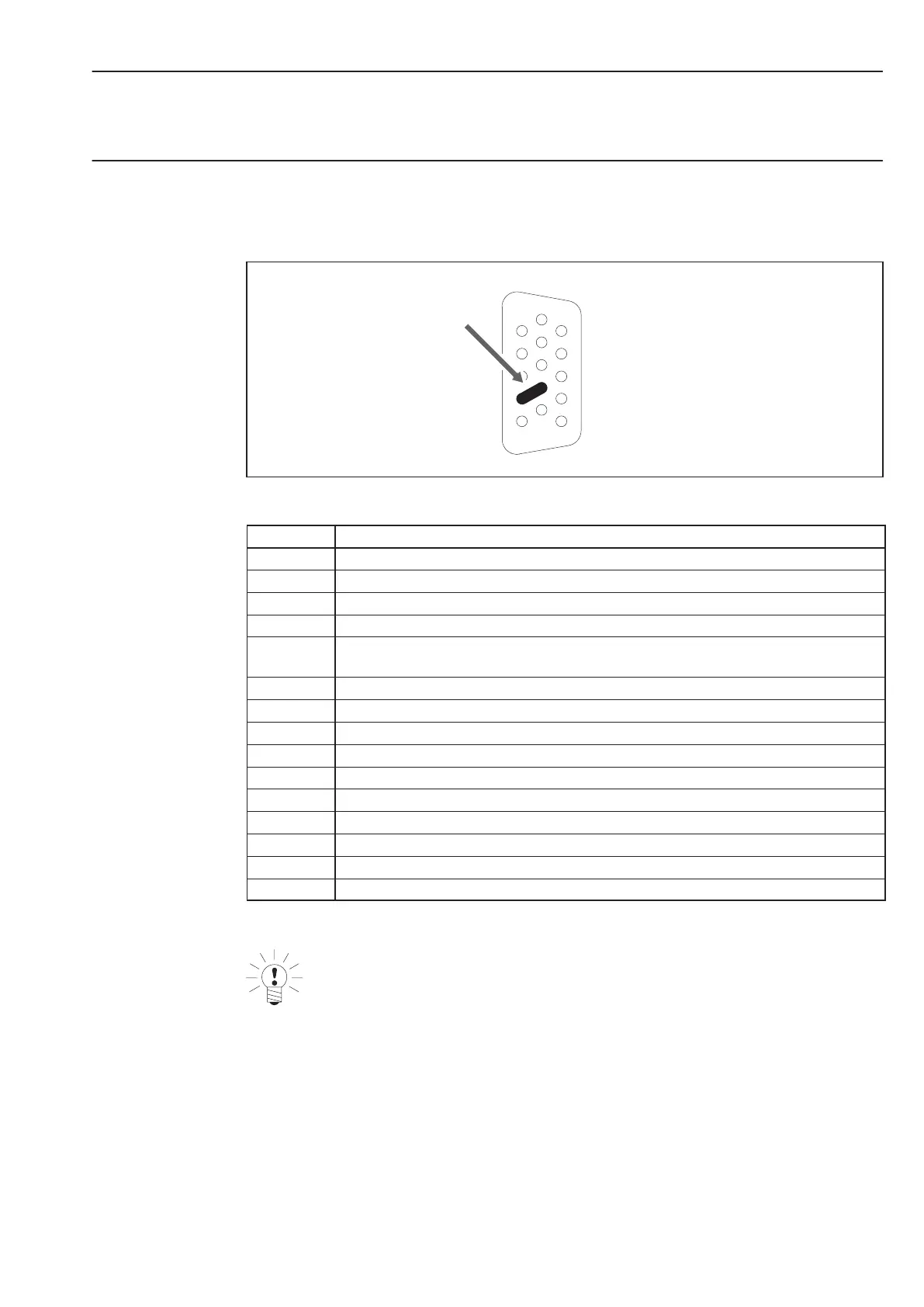
So that insertion or removal of a transducer connection can be unmistakably identified, Pin 4
and Pin 9 in the connector plug must be bridged! If this bridge is missing, no measurement
values will be recorded at the connection!
1
4
5
6
9
11
15
Bridge
Fig.6.4: Pin arrangement of connection plug, view from the solder side
Pin Connection
1 TEDS (+)
2 Bridge Excitation voltage (−), 0° reference pulse (zeroing pulse) (−)
3 Bridge Excitation voltage (+), 0° reference pulse (zeroing pulse) (+)
4 Always connect with Pin 9! (Plug identification)
5 Measurement signal (+), potentiometer measurement signal(+),
voltage input 100 mV (+), f
1
(−) signal differential, SSI data (−)
6 TEDS (−), ground frequency measurement
7 Sense lead (−), f
2
(−) signal differential, CAN-High, SSI clock (−)
8 Sense lead (+), f
2
(+) signal differential, CAN-Low, SSI clock (+)
9 Signal ground
10 Measurement signal (−), f
1
(+) signal differential, SSI data (+)
11 Active sensor supply 5 ... 24 V (0 V)
12 Active sensor supply 5 ... 24 V (+)
13 Current input "30 mA (+)
14 Voltage input 10 V (+), 60 V (+)
15 Calibration signal T10F(S) and T40, 5 V/max. 10 mA
NOTE
Many HBM transducers are fitted with 15-pin D-SUB connectors (2 rows). The adapter
cable 1-KAB416 can be used for connection to the 3 row D-SUB-15HD device
connectors of the MX840. Pins 4 and 9 are already bridged in this adapter cable (see
chapter 9.4.3).