123Connection
HBMQuantumX
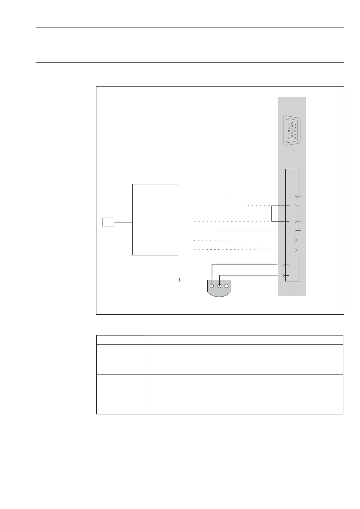
Connection diagram for MX840, MX840A, MX440A with external Smart module:
9
4
Hsg.
14
(−)
(+)
Cable shield
Supply voltage zero
6
1
123
1
5
6
10
11
15
2 Data
3 No function
1
12
11
24 V
0 V
white
green
red
black
PIN:
2
6
3
5
4
Smart module
(1−EICP−B−2)
IEPE
BNC
1-wire EEPROM (optional)
(view from below)
Hsg. = housing
Maximum input voltage to housing and signal
ground : "60 V
Accessories for connecting the Smart module:
Product Description Order No.:
Smart module
External 24 V signal conditioning module,
supplying IEPE with constant current (BNC
socket) and feeding standardized " 10 V voltage
signal.
1−EICP−B−2
Connection
cable
Cable between Smart module and SubHD plug
1−SAC−EXT−MF−x
−2 (x = length in
meter)
Male device
connector
QuantumX connector 1−SubHD15−MALE
 Loading...