5 June 2020 CasTemp Wireless including CasTemp Superheat Page 12
3.1.1.1 QUBE CTW module with USB-A inlet
• Lift up the Harting cover but DO NOT remove.
• Ensure QUBE CTW module charge socket is clean and undamaged.
• Plug in the USB plug end of the CTW CHARGING CABLE into the dedicated USB charging
port socket on the QUBE CTW module
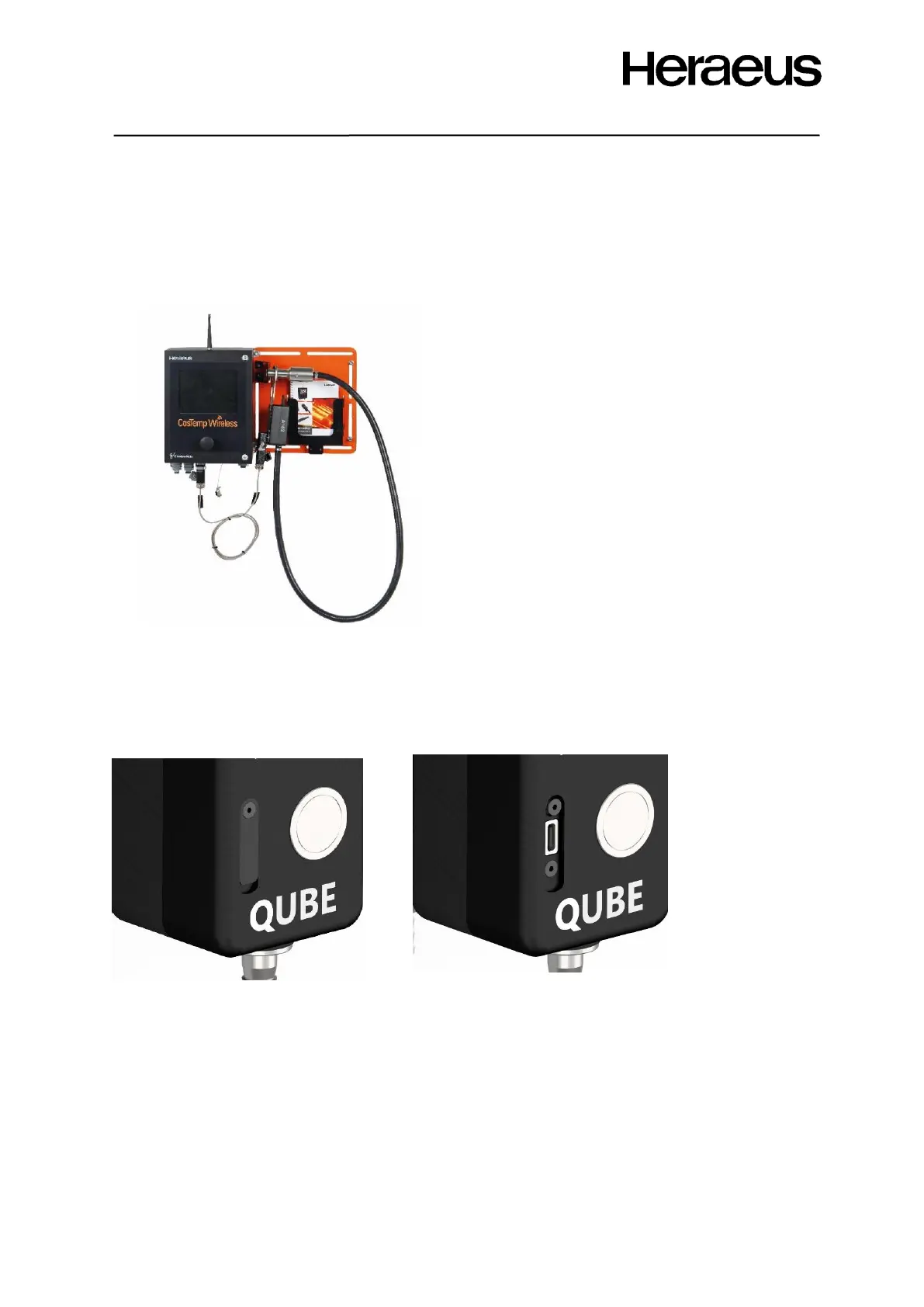
Figure 9 shows the assembled instrument mounting
plate, CasTemp Wireless instrument and QUBE CTW
module in charging position on the mounting plate.
3.1.1.2 QUBE CTW module with USB-C inlet
• Lift up the retaining flap on the QUBE CTW module but DO NOT remove.
• Plug in the USB plug end of the CTW CHARGING CABLE into the dedicated USB charging
port socket on the QUBE CTW module as shown in Figure 10
NOTE: For both QUBE CTW module USB-A and USB-C variants:
• No lights will be indicated on the QUBE CTW module unless the button (shown in Figure 18)
is pressed however the battery will be charging.
• If the button is pressed then the battery and measurement LED’s are shown as in sections
4.2.2.4 and 4.2.2.4
• The cable can be left connected when the charge level reaches 100%. The software will
ensure that the charging circuit is protected and battery level remains topped up.