Operating tabletop mechanical components
4990851_002_00 – 2082262 – 2022-01-10 31
7.2 Pad plate
The struts are joined together by pad plates and the transverse
web. After loosening or removing both pad plates, the struts can
be moved to a certain extent in relation to each other. If possible,
loosen and remove a maximum of 1 pad plates. Even minor
differences in length between the right and left strut will
subsequently prevent the section segments from engaging at the
coupling points. As a result, the struts must be realigned
lengthwise as soon as both pad plates have been loosened or
removed.
Attention: When both pad plates are removed, pressure on the
struts can result in the deformation of the transverse web. Do not
lean or press on the struts.
Removal 1. Prepare the operating table (Chapter 5).
2. Disconnect the power supply on the operating table
(Chapter 6.1).
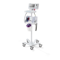
3. Note the mounting position of the pad plate. Remove the pad
plate [1] from the struts [2].
– Seat section pad plate (8 screws)
– Back section pad plate (6 screws)
Assembly 1. Check the hook straps on the pad plate and replace if worn
or damaged.
A new pad plate must be fitted with a new velcro tape (for the
seat section only). The velcro tape has a self-adhesive
backing.
a) Thoroughly clean and degrease the pad plate in the area
of the velcro tape.
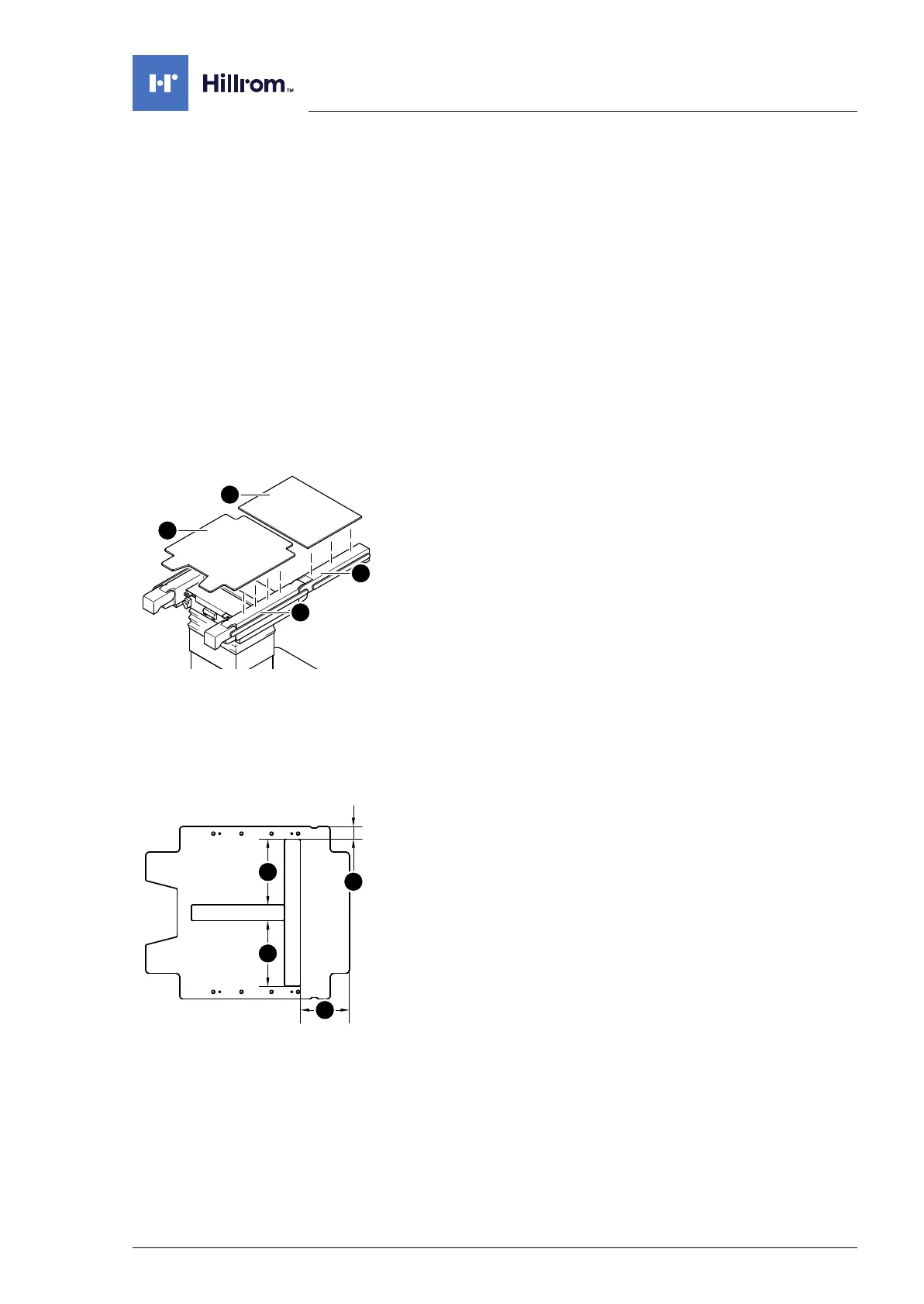
b) Stick the new velcro tape onto the pad plate in
accordance with the specified dimensions.
2. Align struts lengthwise (Chapter 16.1).
Alignment of the struts is required only if both pad plates are
removed.
3. Return the pad plate to its original mounting position.
Position and attach the pad plate onto the struts:
– Seat section pad plate (8 screws)
– Back section pad plate (6 screws)
4. Put the pad in place.
5. Connect the power supply to the operating table
(Chapter 6.2).
[A] 40 mm (1.5748 in)
[B] 207.5 mm (8.1693 in)
[C] 155 mm (6.1024 in)
 Loading...