Operating tabletop mechanical components
4990851_002_00 – 2082262 – 2022-01-10 37
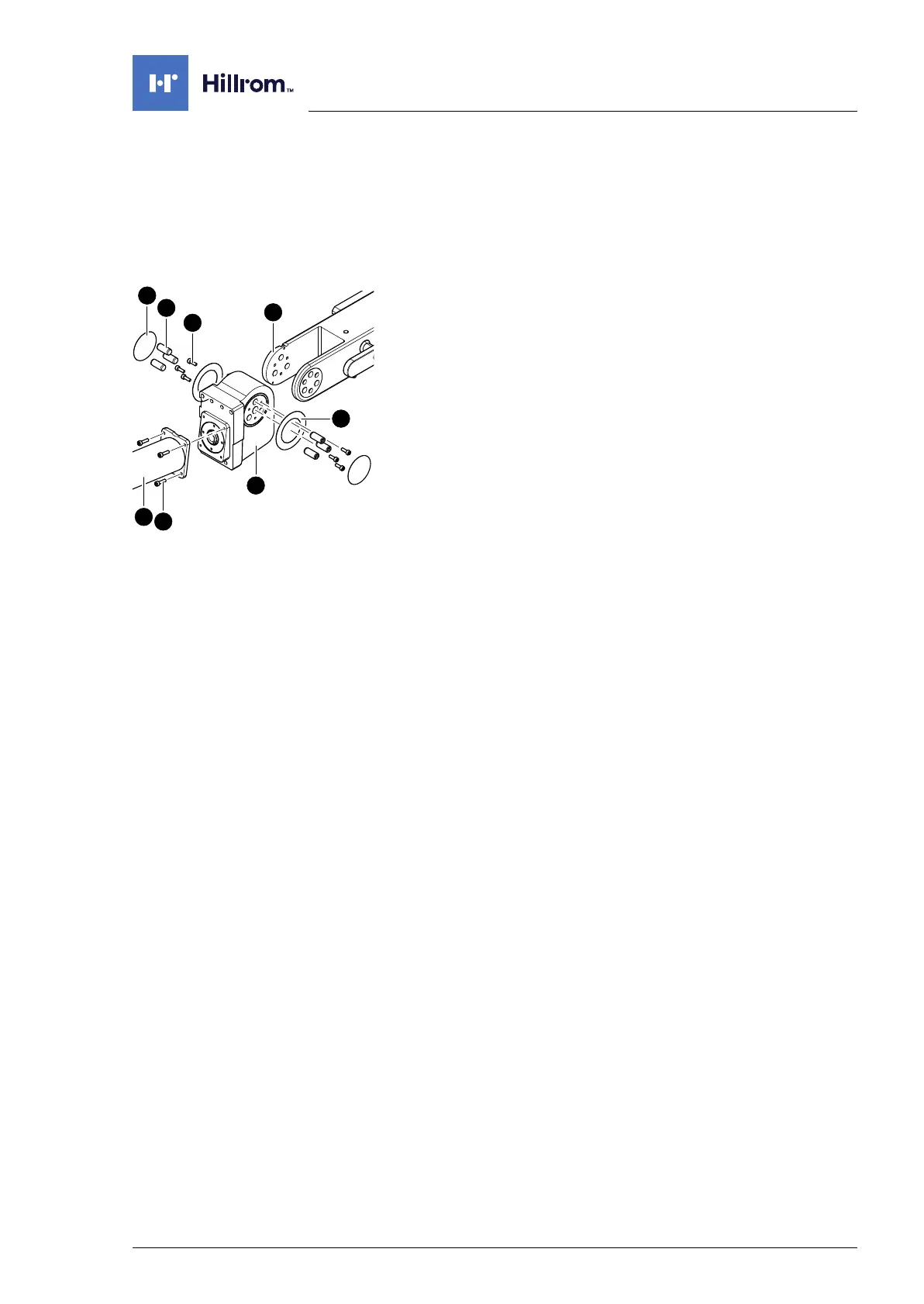
7.6 Gear unit back section
Removal 1. Prepare the operating table (Chapter 5).
2. Disconnect the power supply on the operating table
(Chapter 6.1).
3. Remove the pad plate from the seat section and the back
section (Chapter 7.2).
4. Remove the back section drive unit (Chapter 8.4).
5. Note the mounting position of the motor. Unscrew the
motor [1] from the back section gear [2] (4 screws [3]) and
remove.
6. Remove both self-adhesive protective sheets [4] laterally
from the back section hinge [5].
7. Remove 6 cylindrical pins [6] using a pin remover.
8. Remove 6 screws [7].
9. Remove the hinge [5] from the gear [2] and remove 2 sliding
washers [8].
Assembly 1. Check sliding washers and replace if worn or damaged.
2. Press the sliding washers onto the lip seals and push the
hinge onto the back section gear.
Make sure the sliding washers are properly positioned.
3. Insert the 6 cylindrical pins.
4. Mount the 6 screws.
5. If necessary, attach new self-adhesive protective sheets
laterally onto the back section hinge.
6. Restore the motor to its original mounting position. Mount
the motor onto the back section gear (4 screws).
7. Mount the back section drive unit onto the seat section bar
(Chapter 8.4).
8. Align the hinges (Chapter 16.2).
9. Align struts lengthwise (Chapter 16.1).
10. Mount the pad plates onto the strut (Chapter 7.2).
11. Put the pad in place.
12. Connect the power supply to the operating table
(Chapter 6.2).