Tabletop cables
96
4990851_002_00 – 2082262 – 2022-01-10
13.4 Back section hinge sensor (W502/W507)
Removal 1. Prepare the operating table (Chapter 5).
2. Disconnect the power supply on the operating table
(Chapter 6.1).
3. Remove the pad plate from the seat section (Chapter 7.2).
Attention: Leave the pad plate on the back section attached
so that the adjustment of the struts is maintained.
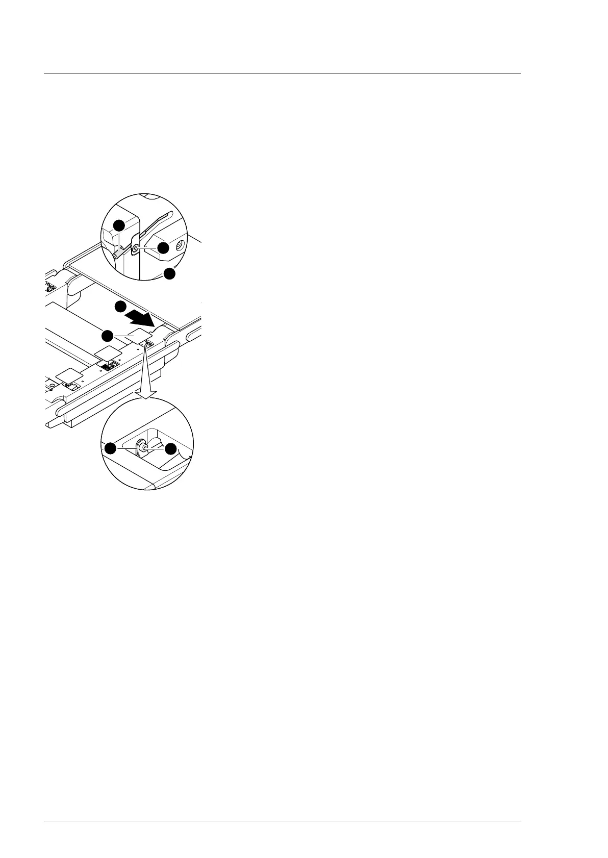
4. Remove the self-adhesive protective sheet [1] from the head-
end and centre opening on the strut.
5. Remove the back section hinge sensor [2] and the retaining
plate (1 screw [3]).
6. Remove the cable clip [4] in the seat section bar through the
opening (1 screw [5]).
7. Note the cable routing. Pull the plug of the sensor cable
W502/W507 [2] from the socket of cable W202/W303
through the opening in the seat section bar.
8. Return the sensor to the strut and take out through the
opening in the seat section bar.
Assembly 1. Carefully guide the sensor through the opening in the seat
section bar into the strut.
Make sure that the insulation of cable is not damaged.
2. Attention: Do not interchange the plug connections. Pay
attention to the wiring diagram on page 64.
Restore the original cable routing. Insert the plug of sensor
cable W502/W507 into the W202/W303 cable bushing.
3. Switch on the operating table using the switch at the running
gear.
4. Adjust the sensor back section hinge.
The end position of the back section hinge is set on the left
hinge and the zero position of the back section hinge is set on
the right hinge.
a) Carefully shift the back section hinge into the switching
position.
b) The gap between the sensor and hinge must be 0.3 mm to
0.5 mm. Position the sensor accordingly.
5. Switch off the operating table using the switch at the running
gear.
6. Mount the sensor back section hinge and the retaining plate
(1 screw).