Column mechanical components
4990851_002_00 – 2082262 – 2022-01-10 55
9.3 Column head cover
Removal 1. Prepare the operating table (Chapter 5).
2. Disconnect the power supply on the operating table
(Chapter 6.1).
3. Remove the pad plate from the seat section (Chapter 7.2).
Attention: Leave the pad plate on the back section attached
so that the adjustment of the struts is maintained.
4. Remove the cassette rails on the foot end from both seat
section struts (2 screws each) so that the screws of the
column head cover become accessible.
5. Switch on the operating table using the switch at the running
gear.
6. Shift the longitudinal slide of the tabletop to the extreme
head end position to expose the column head cover.
7. Switch off the operating table using the switch at the running
gear.
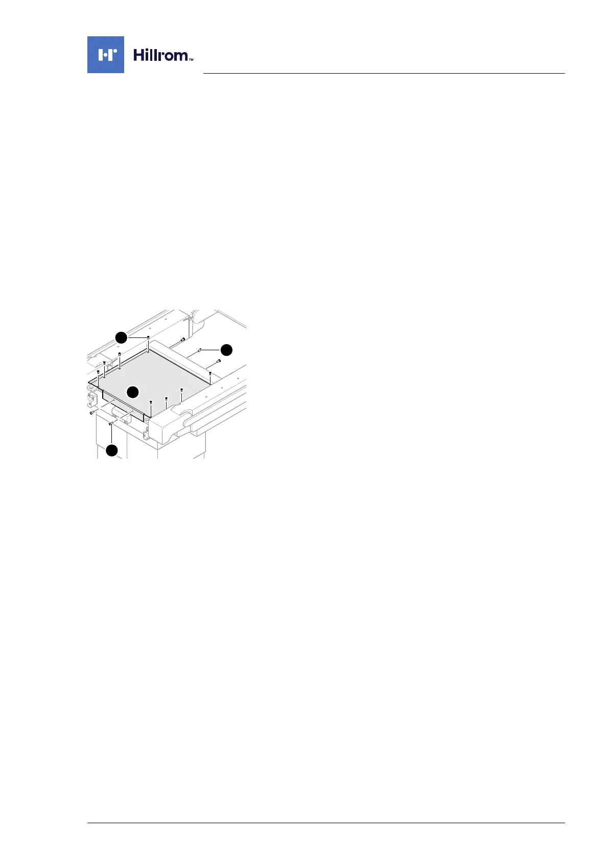
8. Remove the column head cover [2] (8 screws [5] from above,
4 screws [3] at the head end and 2 screws [4] at the foot end).
Assembly 1. Mount the column head cover (8 screws from above, 4
screws at the head end and 2 screws at the foot end). If
necessary, switch on the operating table at the switch and
move the tabletop longitudinal slide in such a way that all 8
holes of the column head cover are accessible.
2. Mount the foot-end cassette rails on both seat section struts
(2 screws each).
3. Mount the pad plate onto the strut (Chapter 7.2).
4. Put the pad in place.
5. Connect the power supply to the operating table
(Chapter 6.2).