Column electric components
4990851_002_00 – 2082262 – 2022-01-10 63
10.2 Lift motor assembly
Attention: the lift motor assembly requires a serial number.
Observe Chapter 1.9 when replacing the assembly.
Removal 1. As far as is still possible, prepare the operating table
(Chapter 5).
2. Disconnect the power supply on the operating table
(Chapter 6.1).
3. Turn over the operating table (Chapter 6.7).
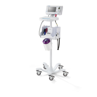
4. Remove the protective sheet [1] from the bottom of the
running gear.
5. Remove the base cover [2] from the running gear (7 screws).
6. If manual adjustment of the lift position is required, remove
the cover plate [3] from the spindle end (securing ring pliers)
and crank the lift spindle [4] up using a socket wrench.
7. Loosen the lift motor assembly [4] (4 screws [5]).
8. Note the cable routing. Disconnect the plug of the motor
connection cable W102 from the main board.
9. Remove the cover plate [6] from the cogged belt (lift motor)
(5 screws).
10. Disengage the cogged belt [7] from the sprocket on the lift
motor.
11. Hold the lift motor assembly [4] securely and unscrew from
the column base (4 screws [5]).
12. Note the mounting position of the lift motor assembly.
Carefully remove the lift motor assembly [4] from the
column.
Assembly 1. Restore the original mounting position of the lift motor
assembly (position of the motor mount). Insert the lift motor
assembly and precisely place the cogged belt around the
sprocket. Be careful that the teeth of the sprocket and on the
cogged belt grip securely into each other (and tooth-to-tooth
contact is avoided). If necessary, move the motor back and
forth a little.
2. Fix the lift motor into place on the column end (4 screws, do
not tighten yet!). The motor mounting bracket must still be
easy to move.
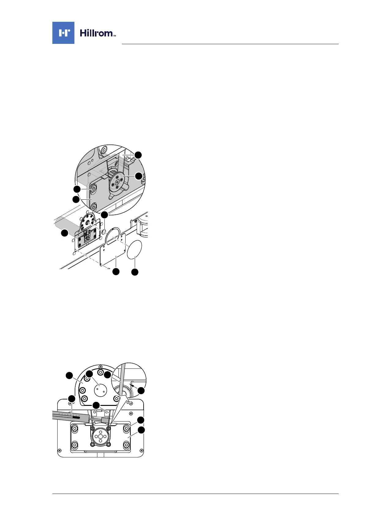
3. Tighten the cogged belt.
a) A second person is required for tensioning the cogged
belt and mounting the lift motor assembly.
b) Press the spring scale [8] against the cogged belt [7] from
the inside, in accordance with the diagram.
c) Press the spindle [9] and lift motor assembly [4] apart
using a tommy bar.
d) Adjust the distance between the spindle and the lift motor
assembly in such a way that the force applied reads
between 15 N and 20 N on the spring scale, and that there
is only a light gap at the marked location [A].
e) Tighten 4 screws [5] on the lift motor assembly.