Running gear electric components
86
4990851_002_00 – 2082262 – 2022-01-10
12.7 Voltage selector circuit board
Attention: the voltage selector circuit board requires a serial
number. Observe Chapter 1.9 when replacing the circuit board.
Removal 1. Prepare the operating table (Chapter 5).
2. Disconnect the power supply on the operating table
(Chapter 6.1).
3. Open the column cover on the running gear (Chapter 6.3).
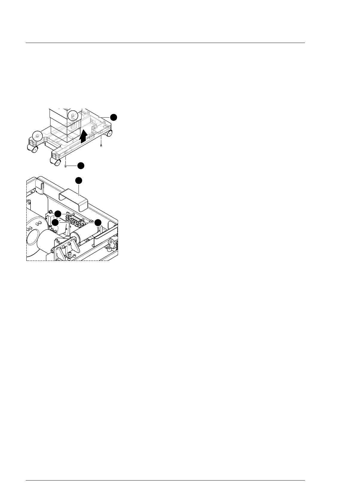
4. Loosen the running gear metal cover [1] (4 screws [2]).
5. Push up the running gear metal cover [1] and fix in the upper
position.
6. Remove the cover [6] of the circuit board from the
spacers [5].
7. Note the cable routing. Remove the cable fastenings for the
cables to the voltage selector circuit board [3] if necessary.
8. Note the cable routing. Disconnect all plugs from the voltage
selector circuit board [3].
9. Remove the voltage selector circuit board [3] (4 screws [4]).
10. Remove the spacer [5] from the circuit board.
Assembly 1. Mount the spacer on the circuit board.
2. Mount the voltage selector circuit board (4 screws).
3. Attention: Do not interchange the plug connections. Pay
attention to the wiring diagram on page 64.
Restore the original cable routing. Connect all plugs to the
voltage selector circuit board.
4. Restore the original cable routing. Mount any cable
fastenings removed from the cables of the voltage selector
circuit board.
5. Press the cover of the circuit board onto the spacers until you
feel it lock in place.
6. Mount the running gear metal cover on the running gear
(Chapter 11.2).
7. Guide the column cover downwards and close on the running
gear (Chapter 6.4).
8. Put the pad in place.
9. Connect the power supply to the operating table
(Chapter 6.2).