Column mechanical components
60
4990851_002_00 – 2082262 – 2022-01-10
9.7 Lift spindle cogged belt
Removal 1. As far as is still possible, prepare the operating table
(Chapter 5).
2. Disconnect the power supply on the operating table
(Chapter 6.1).
3. Turn over the operating table (Chapter 6.7).
4. Remove the protective sheet [1] from the bottom of the
running gear.
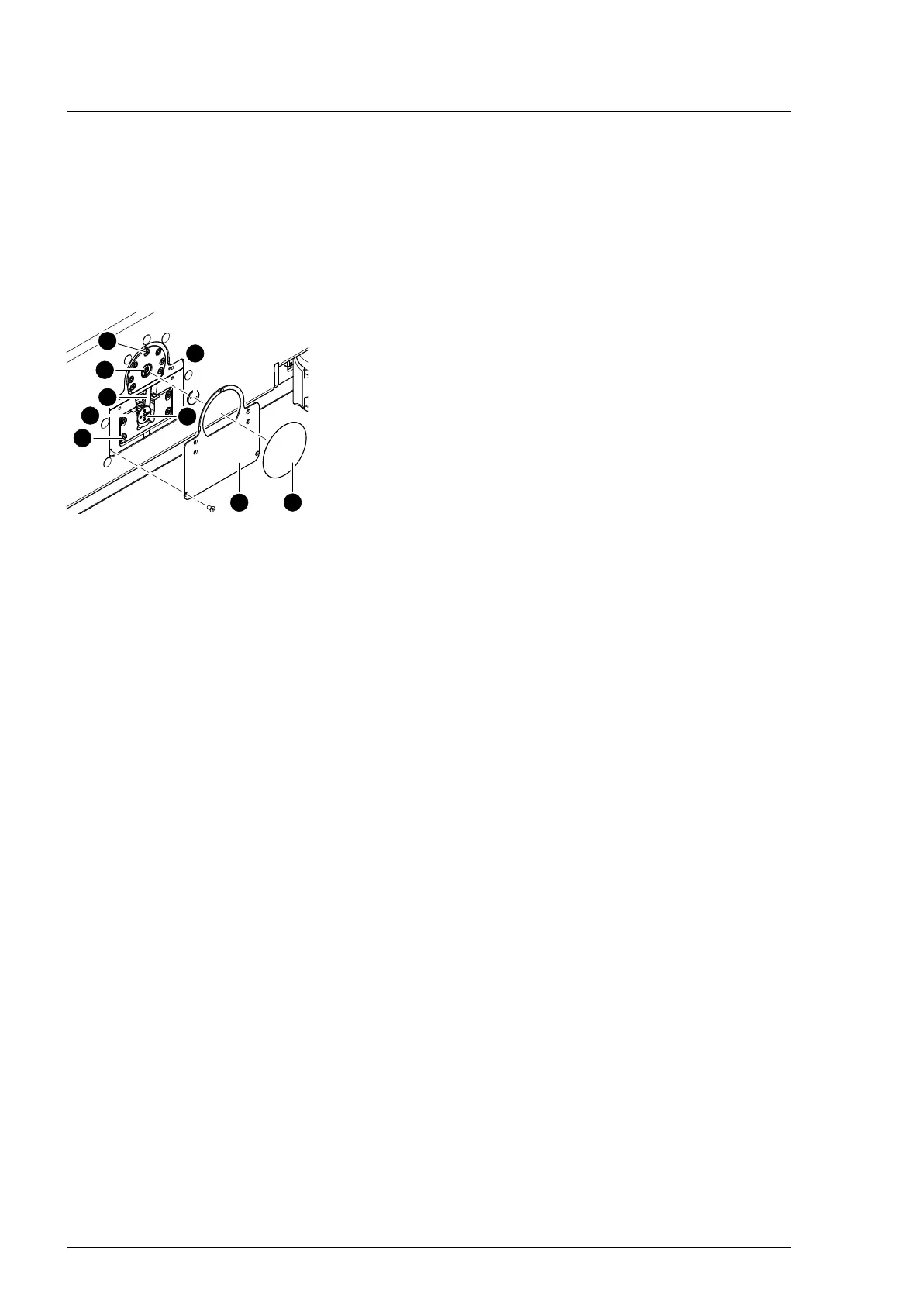
5. Remove the base cover [2] from the running gear (7 screws).
6. If manual adjustment of the lift position is required, remove
the cover plate [3] from the spindle end (securing ring pliers)
and crank the lift spindle [4] up using a socket wrench.
7. Loosen the lift motor assembly [5] (4 screws [6]).
8. Remove the 7 screws [7] on the bearing housing of the
spindle. The screws attach the spindle foot to the base of the
operating table.
9. Remove the cover plate [8] from the cogged belt (lift motor)
(5 screws).
10. Disengage the cogged belt [9] from the sprocket on the lift
motor [5].
11. Remove the cover plate [3] from the spindle end
12. Use a socket wrench to crank up the lift spindle [4].
During this operation, the spindle foot will slide out of the
running gear and the cogged belt will become accessible.
13. Remove the cogged belt.
Assembly 1. Place the cogged belt around the sprocket of the lift spindle.
Be careful that the teeth of the sprocket and on the cogged
belt grip securely into each other (and tooth-to-tooth contact
is avoided).
2. Use a socket wrench to crank down the lift spindle until the
spindle foot touches the floor of the operating table. In doing
so, route the drive belt under the brace of the base plate.
3. Place the cogged belt around the sprocket on lift motor. Be
careful that the teeth of the sprocket and on the cogged belt
grip securely into each other (and tooth-to-tooth contact is
avoided).
4. Mount the cover plate on the sprocket (lift motor) (5 screws).
5. Fix the lift motor into place on the column end (4 screws, do
not tighten yet!). The motor mounting bracket must still be
easy to move.
6. Install the bearing housing of the spindle on the base of the
operating table (7 screws). Tighten the screws with a torque
of 10 Nm.
 Loading...