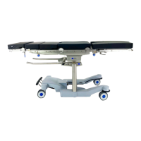
Column electric components
68
4990851_002_00 – 2082262 – 2022-01-10
10.4 Edging assembly
Attention: the edging assembly requires a serial number. Observe
Chapter 1.9 when replacing the assembly.
Removal 1. Prepare the operating table (Chapter 5).
2. Disconnect the power supply on the operating table
(Chapter 6.1).
3. Remove the pad plate from the seat section (Chapter 7.2).
Attention: Leave the pad plate on the back section attached
so that the adjustment of the struts is maintained.
4. Remove the column head cover (Chapter 9.3).
5. Open the column top and guide the column cover
downwards (Chapter 6.5).
6. Switch on the operating table using the switch at the running
gear.
7. Move the tabletop edging to the right (end position) if
possible.
8. Switch off the operating table using the switch at the running
gear.
9. Note the cable routing. Remove the cable fastening from the
edging assembly.
10. Note the cable routing. Disconnect the plug of the tilting
assembly connecting cable from the main board in the Main
Controller Unit.
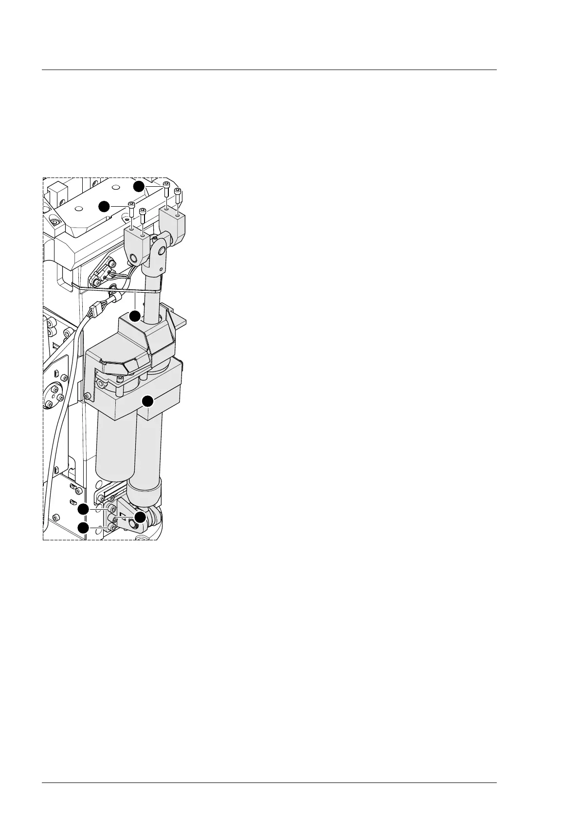
11. Secure the edging assembly [1] to the column using cable
ties [2].
12. CAUTION! The operating tabletop may tip over if the edging
assembly is loosened. Before continuing disassembly, secure
the tabletop from tipping over using lashing straps, chocks or
suitable auxiliary tools.
13. Remove the edging assembly [1] from the top of the tabletop
(4 screws [3]).
14. Securely hold the edging assembly.
15. Release the bottom of the edging assembly plate.
a) Pull out both bolts [4] (lifting aid).
b) Remove 8 screws [5] with nuts.
16. Remove the cable tie [2].
17. Remove the edging assembly [1] and safely place on a level
work surface.
Assembly 1. Fix the lower edging assembly plate into place (8 screws with
nuts, do not tighten).
2. Punch both bolts into the lower edging assembly plate.
The bolts must still protrude about 5 mm. In the case of bolts
that have been punched in too far, there is a risk of colliding
with lift spindle bearing block.
3. Mount the lower edging assembly plate onto the column (8
screws with nuts, tighten).
4. Fix the edging assembly to the column using cable ties.
5. Mount the edging assembly on top of the tabletop (4 screws).
Tighten the screws with a torque of 10 Nm.