Operating tabletop mechanical components
38
4990851_002_00 – 2082262 – 2022-01-10
7.7 Cogged belt back section
Removal 1. Prepare the operating table (Chapter 5).
2. Disconnect the power supply on the operating table
(Chapter 6.1).
3. Remove the pad plate from the seat section (Chapter 7.2).
Attention: Leave the pad plate on the back section attached
so that the adjustment of the struts is maintained.
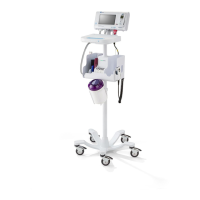
4. Remove the self-adhesive protective sheet [1] from the
centre opening on both struts.
5. Remove the cogged belt cover [2] (4 screws [3]).
6. Release the clamping device [4] for the belts on both back
section drive units (2 screws each).
7. Release the cable clip [5] on a drive unit (1 screw).
8. Slightly loosen the tensioning screw [6] on the clamping
device [4]. Where necessary, ensure that the tensioning
screw on the other clamping device is also slightly loosened.
9. Note the mounting position of the cogged belt. Do not twist
the sprocket on the motor.
Disengage the cogged belt [7] on both drives.
10. Pull the cogged belt [7] through the struts and remove.
Assembly 1. Check the alignment of the right and left hinges in relation to
each other. The two hinges must be at the same height.
Adjust the hinges if necessary (Chapter 16.2).
2. Restore the cogged belt to its original mounting position.
Carefully put the new cogged belts into both of the seat
section bars at the ends and place them in the bridge
(between the cogged belt guides).
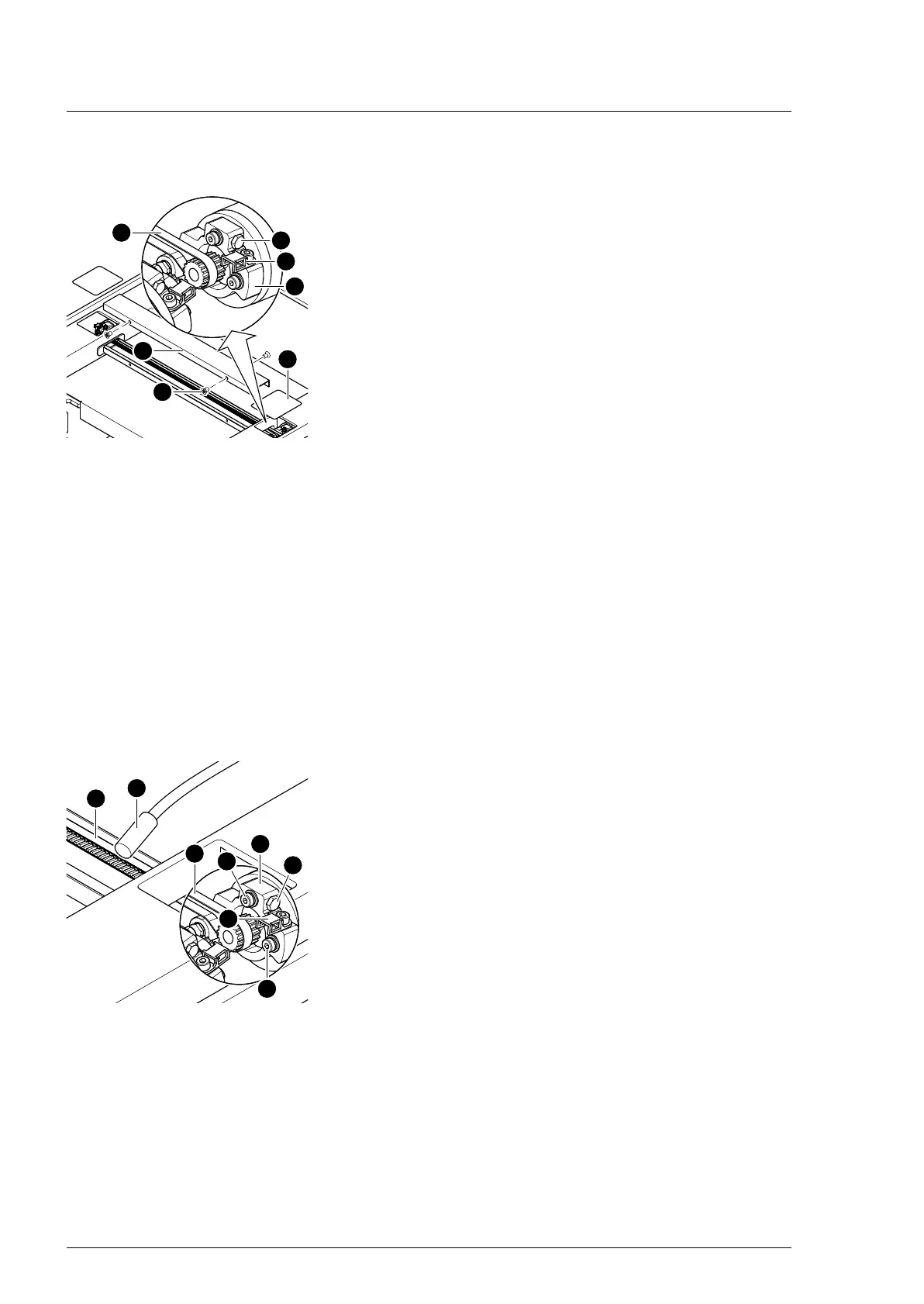
3. Suspend the cogged belt.
Ensure that the cogged belt is properly guided over the
clamp roller. The cogged belts must run parallel.
4. Adjust the cogged belt.
Evenly tension the cogged belt on both sides.
a) Screw in the tensioning screw [6] on both clamping
devices [4].
b) Determine the cogged belt oscillation frequency using a
tension meter device [9] and readjust the cogged belt
tension where necessary using the tensioning screw(s) [6]
(pre-tensioning 49 Hz ± 3 Hz, check 3x in succession).
c) Mount the clamping device [4] for the belts onto both
drive units for the back section hinge (2 screws [8]).
5. Attach the cable clip [5] onto the drive unit (1 screw).
6. Mount the cogged belt cover (4 screws).
7. Apply new self-adhesive protective sheets to the middle
openings on both struts.
8. Mount the pad plate onto the strut (Chapter 7.2).
9. Put the pad in place.
10. Connect the power supply to the operating table
(Chapter 6.2).
 Loading...