Basic work
4990851_002_00 – 2082262 – 2022-01-10 25
6.5 Open column top
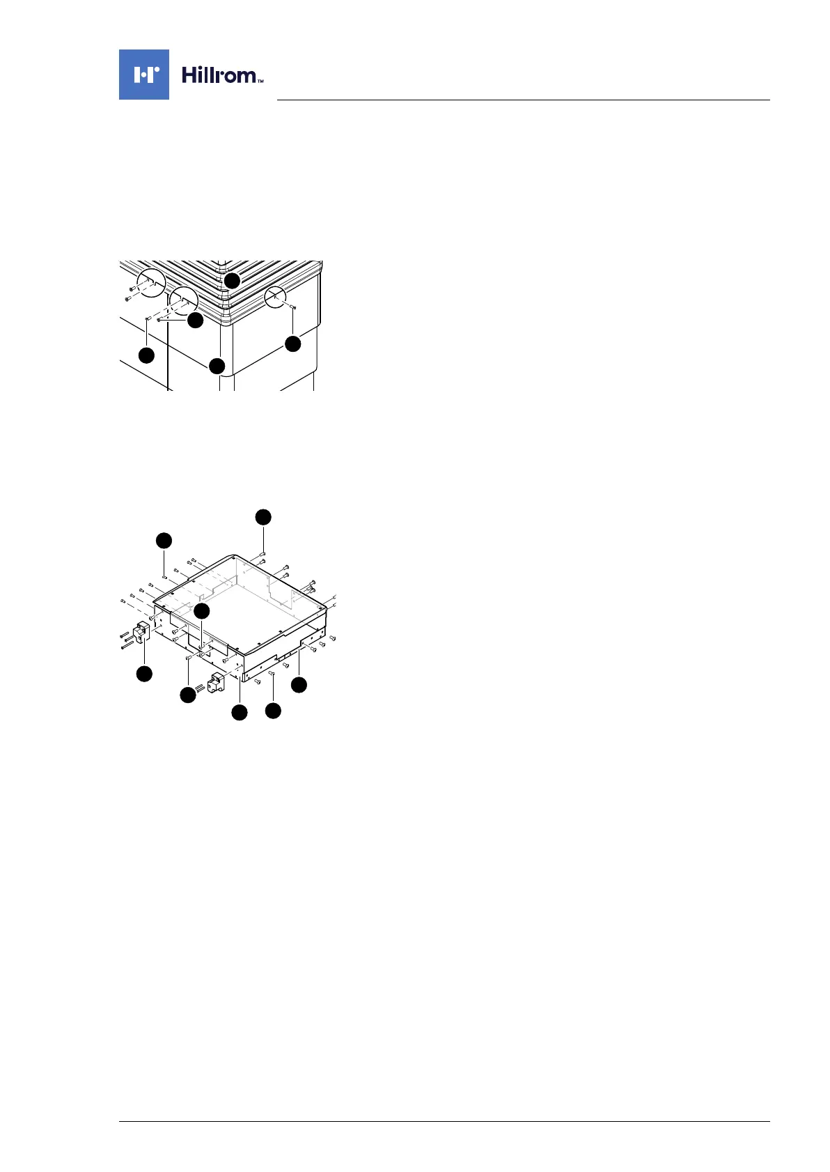
To obtain access to the internal components, remove the column
cover from the bellows and lower it onto the running gear. Next,
the bellows are detached from the column head.
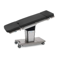
1. Prepare the operating table (Chapter 5).
2. Disconnect the power supply on the operating table
(Chapter 6.1).
3. Release the bellows [1] from the column cover [5] (1 screw [2]
on both the left and the right below the bellows).
4. Release the bellows [1] from the guide column (both the inner
screws [3] below the bellows at the head and foot end).
5. Note the mounting position of the flat conductor. Pull the
bellows upwards and unplug the flat conductor of the column
keypad from the main board (Main Controller Unit).
The flat conductor is clamped to the plug. First push the small
pins at the edge of the plug downwards and then pull the
cable out of the plug.
6. Unscrew the column cover [5] from the frame (4 screws, 1
screw per side) and place it down on the running gear.
Attention - the column cover will slide down as soon as all the
screws have been removed.
7. Remove both carrier blocks [6] for the extension adapter (3
screws each).
8. Switch on the operating table using the switch at the running
gear.
9. Release the two cover plates [7] from the head and foot of
the column head.
Move the longitudinal slide of the operating tabletop as
necessary, so that the lateral screws on the cover plates are
accessible.
a) Remove the upper 6 screws [8] from the foot end of the
column head.
b) Remove the upper 8 screws [9] from the head end of the
column head.
c) Remove 1 screw [10] below the bushing strip at both the
head and foot end of the column head.
d) Remove the upper 6 screws [11] from the left-hand side of
the column head.
e) Remove the upper 8 screws [12] from the right-hand side
of the column head (operator side).
10. Switch off the operating table using the switch at the running
gear.



 To Next Page