Tabletop cables
98
4990851_002_00 – 2082262 – 2022-01-10
13.5 Replace the operating sensor (W508)
Removal 1. Prepare the operating table (Chapter 5).
2. Disconnect the power supply on the operating table
(Chapter 6.1).
3. Remove the pad plate from the seat section (Chapter 7.2).
Attention: Leave the pad plate on the back section attached
so that the adjustment of the struts is maintained.
4. Remove the column head cover (Chapter 9.3).
5. Switch on the operating table using the switch at the running
gear.
6. Shift the longitudinal slide of the tabletop to the zero
position.
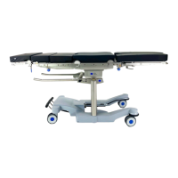
7. Remove both carrier blocks [1] for the extension adapter (3
screws each).
8. Switch on the operating table using the switch at the running
gear.
9. Release the two cover plates [2] from the head and foot of
the column head.
Move the longitudinal slide of the operating tabletop as
necessary, so that the lateral screws on the cover plates are
accessible.
a) Remove the upper 4 screws [3] from the foot end of the
column head.
b) Remove the upper 4 screws [4] from the head end of the
column head.
c) Remove 1 screw [5] below the bushing strip at both the
head and foot end of the column head.
d) Remove the upper 6 screws [6] from the left-hand side of
the column head.
e) Remove the upper 8 screws [6] from the right-hand side
of the column head (operator side).
10. Switch off the operating table using the switch at the running
gear.
11. Loosen the bellows and carefully push downwards.
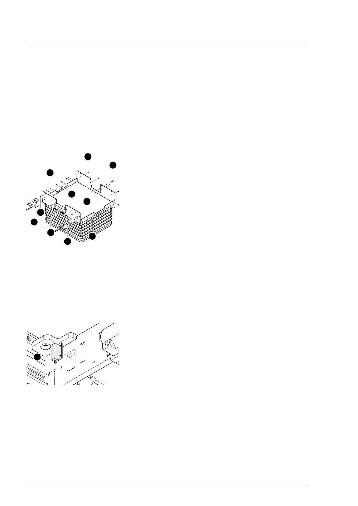
12. Note the cable positions and cable fastenings. Remove cable
fastenings along the sensor cable from the sensor [7] to the
plug connection.
13. Pull the plug of sensor cable W508 from the W304 cable
bushing.
14. Remove the operating sensor [7] with the sensor cable.
Assembly 1. Insert the operating sensor and use adhesive tape to stick
down.
2. Restore the original cable routing. Lay the sensor cable and
restore the cable fastenings.
3. Attention: Do not interchange the plug connections. Pay
attention to the wiring diagram on page 64.
Restore the original cable routing. Insert the plug of sensor
cable W508 into the W304 cable bushing.
4. Carefully guide the bellows with the cover plates upwards.