Column electric components
4990851_002_00 – 2082262 – 2022-01-10 65
10.3 Trendelenburg assembly
Attention: the Trendelenburg assembly requires a serial number.
Observe Chapter 1.9 when replacing the assembly.
The Trendelenburg assembly must be replaced in each case, if the
incline sensor and 1 limit switch are defective. The assembly drive
may have travelled against the position stop of the spindle and
may be defective.
Removal 1. Prepare the operating table (Chapter 5).
2. Disconnect the power supply on the operating table
(Chapter 6.1).
3. Remove the pad plate from the seat section (Chapter 7.2).
Attention: Leave the pad plate on the back section attached
so that the adjustment of the struts is maintained.
4. Remove the column head cover (Chapter 9.3).
5. Switch on the operating table using the switch at the running
gear.
6. Shift the longitudinal slide of the tabletop to the zero
position.
7. Switch off the operating table using the switch at the running
gear.
8. Open the column top and guide the column cover
downwards (Chapter 6.5).
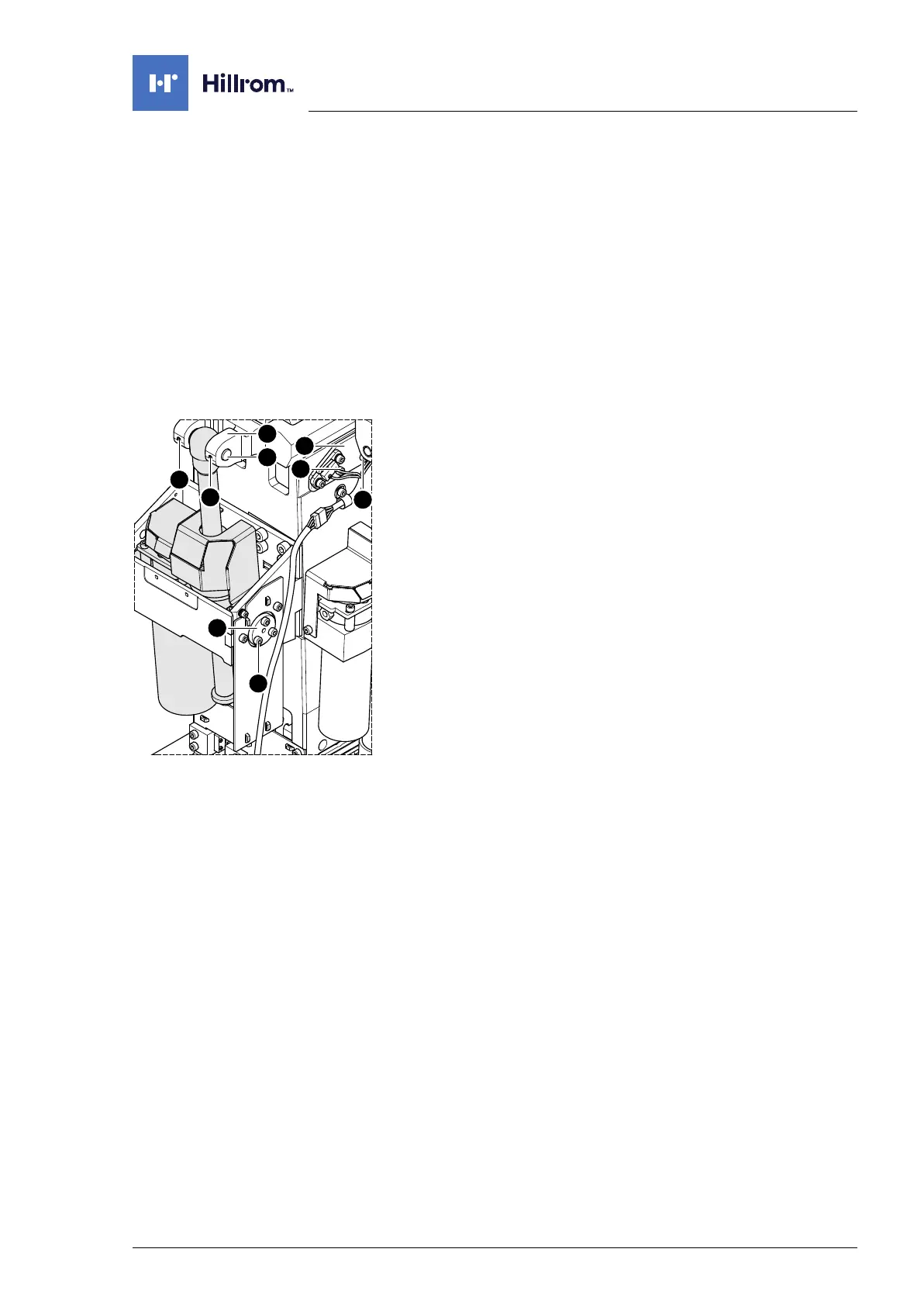
9. Unscrew the sensor plate [1] for the Trendelenburg end stops
(2 screws [2]) and carefully allow it to hang down.
10. Switch on the operating table using the switch at the running
gear.
11. Move the edging of the tabletop 13° to the right (control side).
12. Switch off the operating table using the switch at the running
gear.
13. CAUTION! The operating tabletop may tip over if the
Trendelenburg assembly is loosened. Before continuing
disassembly, secure the tabletop from tipping over using
lashing straps, chocks or suitable auxiliary tools.
14. Unscrew 2 screws [3] from the fork mount [4].
15. Knock the Trendelenburg bolt [5] out of the fork mount [4].