Column electric components
66
4990851_002_00 – 2082262 – 2022-01-10
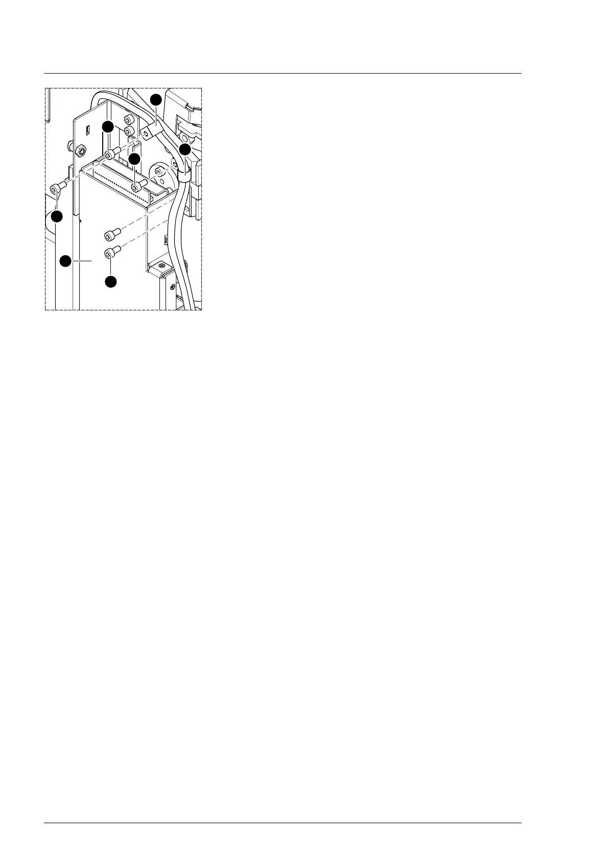
16. Remove 2 cable clips [8] above the Main Controller Unit [10] (1
screw each [9]).
17. Loosen the Main Controller Unit [10] from the Trendelenburg
mount (3 screws [11]).
18. Note the cable routing. Disconnect the plug of the
Trendelenburg assembly connecting cable from the main
board in the Main Controller Unit [10].
19. Secure the Trendelenburg assembly to the column with cable
ties.
20. Remove 5 screws [7] on both Trendelenburg bearing
pivots [6].
21. Securely hold the Trendelenburg assembly.
22. Remove both Trendelenburg bearing pivots [6] using the pin
remover.
23. Remove the cable ties.
24. Remove the Trendelenburg assembly and safely place on a
level work surface.
Assembly 1. Remove the cogged belt cover from the new Trendelenburg
assembly (3 screws).
2. Insert the Trendelenburg assembly and fix to the column with
cable ties.
3. Mount both Trendelenburg bearing pivots (5 screws each).
4. Check the tension of the cogged belt and tighten if
necessary (Chapter 16.3).
5. Mount the cogged belt cover (3 screws).
6. Restore the original cable routings and cable fastenings.
7. Check the cable routing and fastening and make sure that
the cable cannot get between moving parts.
8. Mount the Main Controller Unit (3 screws).
9. Mount 2 cable clips above the Main Controller Unit (1 screw
each).
10. Reattach any cable fastenings that have been removed.
11. Switch on the operating table using the switch at the running
gear.
12. Move the edging of the tabletop 13° to the left.
13. Switch off the operating table using the switch at the running
gear.
14. Insert the bolt vertically into the fork mount so that the set
screws meet the flat surface of the bolt.
15. Punch the bolt into the fork mount.
16. Attention: Do not interchange the plug connections. Pay
attention to the wiring diagram on page 64.
Restore the original cable routing. Connect the plug of the
Trendelenburg assembly connecting cable to the main board
(Main Controller Unit).
17. Fit the 2 screws to the fork mount.
18. Remove the tabletop fixing.
19. Switch on the operating table using the switch at the running
gear.
20. Move the edging of the tabletop 13° to the right (control side).