Basic work
26
4990851_002_00 – 2082262 – 2022-01-10
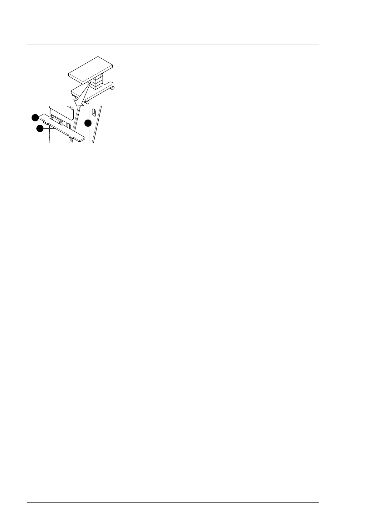
11. Remove the bracket [13] for the bellows on the head end of
the guide column [14] (2 screws [15]).
12. Carefully guide the bellows with the cover plates [7]
downwards.
6.6 Closing the column cover on the bellows
1. Carefully guide the bellows with the cover plates upwards.
2. Switch on the operating table using the switch at the running
gear.
3. Mount the bellows with the head-end and foot-end cover
plates on the column head.
Ensure that the cover plates fit underneath the column head
cover. Move the longitudinal slide of the operating tabletop
as necessary, so that the lateral screws on the cover plates
are accessible.
a) 7 screws at the foot end
b) 9 screws at the head end
c) 8 screws on the right side
d) 6 screws on the left side
4. Switch off the operating table using the switch at the running
gear.
5. Mount the bracket for the bellows on the head end of the
guide column (2 screws).
6. Mount both support blocks for the extension adapter on the
column head (3 screws each).
7. Guide the column cover upwards and mount it at the head
and foot end of both guide column brackets (2 screws each).
8. Return the flat conductor to its original mounting position.
Pull the bellows upwards and push the flat conductor of the
column keypad into the plug of the main board (Main
Controller Unit) and engage. Push the small pins at the edge
of the plug upwards for this purpose.
9. Mount the lower frame of the bellows on both guide column
brackets at the head and foot end (2 screws each).
10. Mount the bellows on the column cover (1 screw each on the
left and right below the bellows).