Column mechanical components
58
4990851_002_00 – 2082262 – 2022-01-10
9.6 Lift spindle
Attention: the lift spindle requires a serial number. Observe
Chapter 1.9 when replacing the lift spindle.
Removal 1. Prepare the operating table (Chapter 5).
2. Disconnect the power supply on the operating table
(Chapter 6.1).
3. Turn over the operating table (Chapter 6.7).
4. Remove the protective sheet [1] from the bottom of the
running gear.
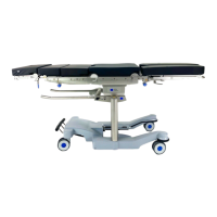
5. Remove the base cover [2] from the running gear (7 screws).
6. If manual adjustment of the lift position is required, remove
the cover plate [3] from the spindle end (securing ring pliers)
and crank the lift spindle [4] up using a socket wrench.
7. Loosen the lift motor assembly [5] (4 screws [6]).
8. Remove the 7 screws [7] on the bearing housing of the
spindle. The screws attach the spindle foot to the base of the
operating table.
9. Remove the cover plate [8] from the cogged belt (lift motor)
(5 screws).
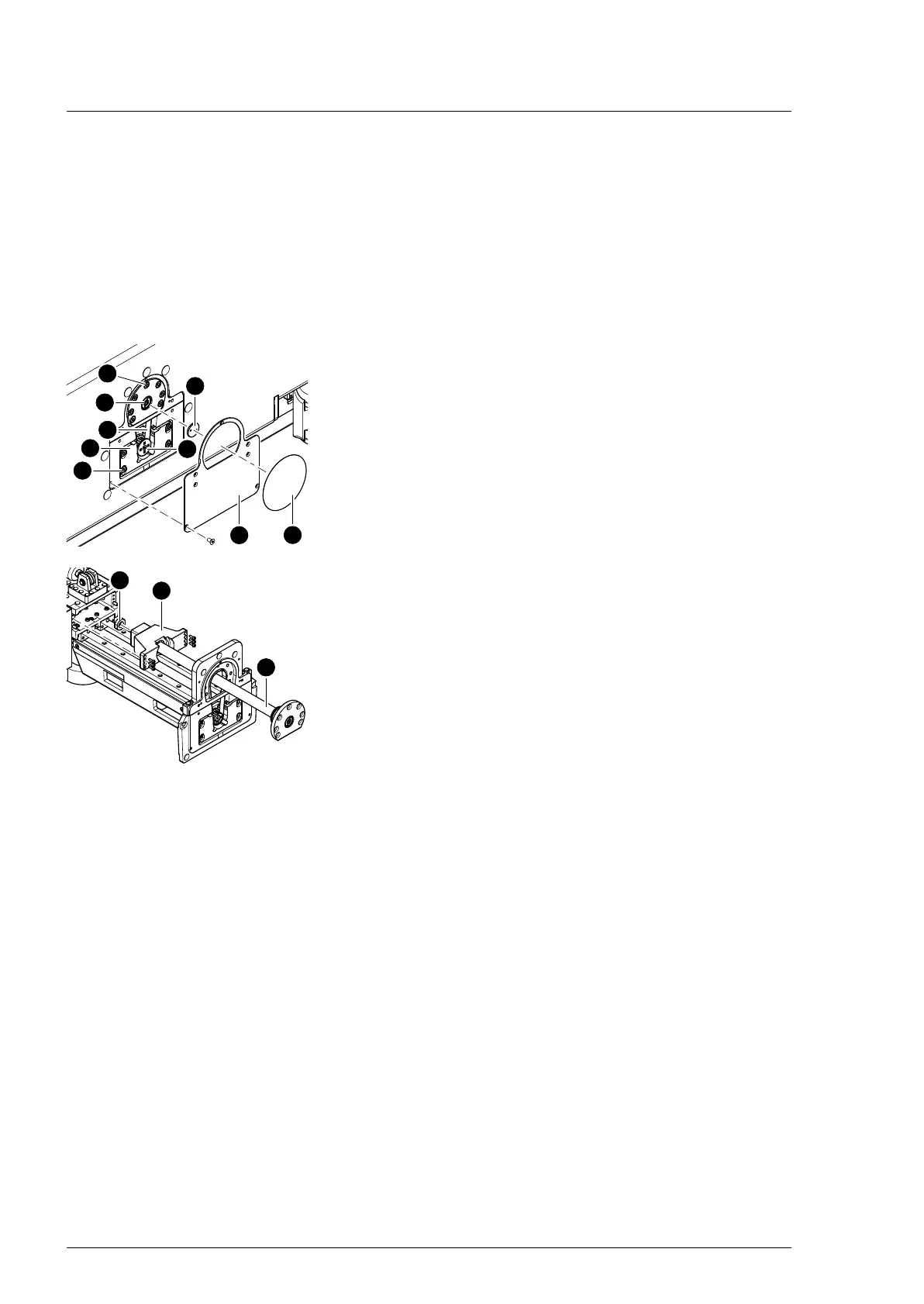
10. Disengage the cogged belt [9] from the lift motor.
11. Release the bearing block [10] of the spindle [11] from the
column duct (6 screws).
12. Carefully remove the spindle [11] and the bearing block [10]
from the column duct.
13. Remove the cap [12] from the upper spindle end.
14. Turn the bearing block [10] off the spindle [11].
15. Remove the spindle [11] from the base of the operating table.
Assembly If a new spindle is to be installed, apply ISOFLEX TOPAS NCA 52
special grease along the entire length of the spindle before
installing it. After installation, operate the lift function a couple of
times and then apply a coat of POLYLUB 151 lubricant along the
entire length of the spindle.
1. Place the bearing block on the column base.
2. Ensure that the mounting position is correct. Screw the lift
spindle into the bearing block through the opening in the
running gear.
3. Apply omniFIT 100M thread locking agent to the internal
thread of the cap and mount the cap to the upper end of the
spindle (pliers).
4. The thread locking agent takes 30 minutes to cure until it
locks properly. Wait 30 minutes until the next step can take
place.
5. Carefully align the spindle with the bearing block in the
column duct.
6. Mount the bearing block on the column duct (6 screws).
Tighten the screws with a torque of 2.5 Nm.