Column mechanical components
4990851_002_00 – 2082262 – 2022-01-10 59
7. Place the cogged belt around the toothed washer of the
spindle. Be careful that the teeth of the sprocket and on the
cogged belt grip securely into each other (and tooth-to-tooth
contact is avoided).
8. Mount the cover plate on the sprocket (lift motor) (5 screws).
9. Fix the lift motor into place on the column end (4 screws, do
not tighten yet!). The motor mounting bracket must still be
easy to move.
10. Install the bearing housing of the spindle on the base of the
operating table (7 screws). Tighten the screws with a torque
of 10 Nm.
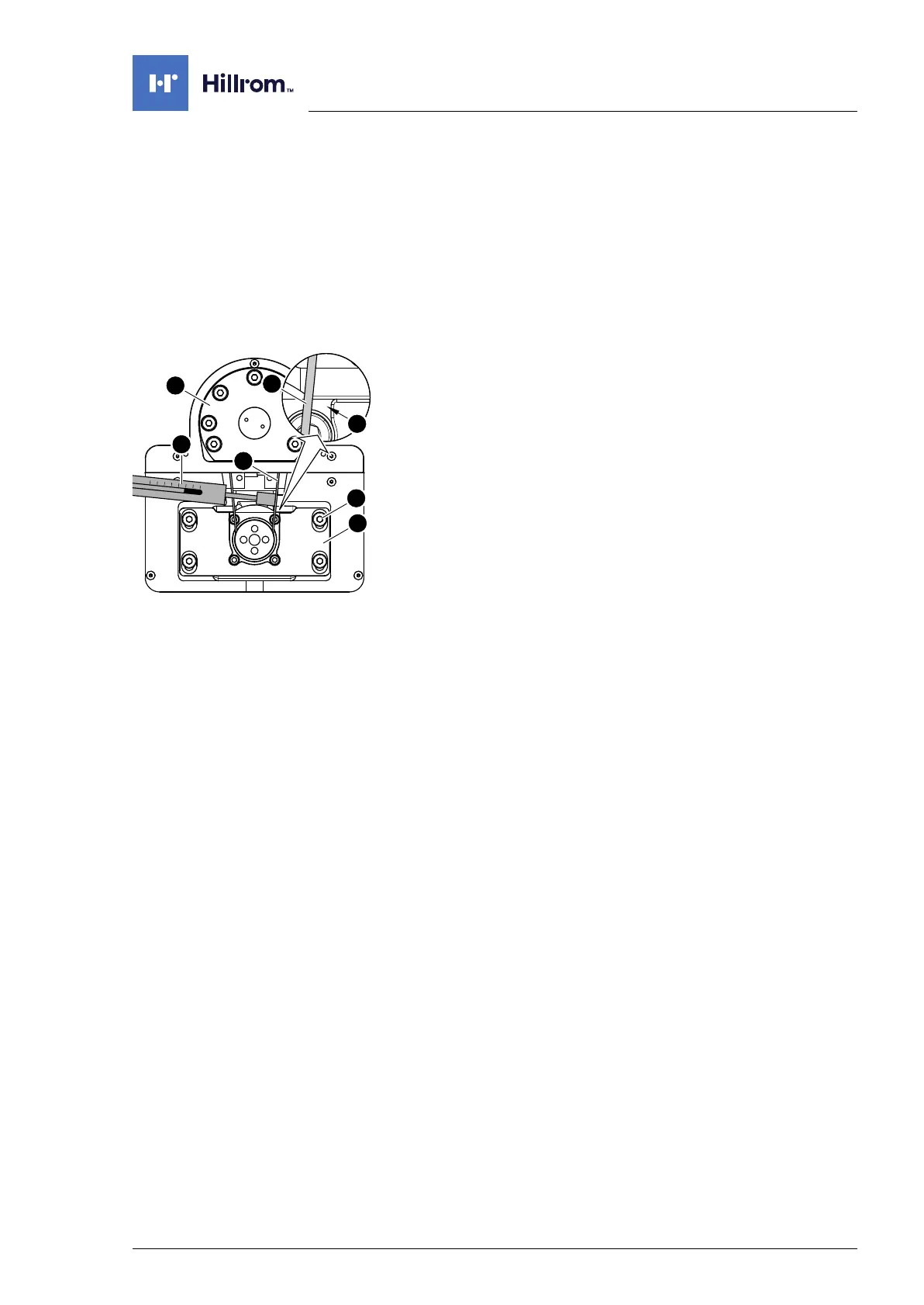
11. Tighten the cogged belt.
a) A second person is required for tensioning the cogged
belt and mounting the lift motor assembly.
b) Press the spring scale [15] against the cogged belt [14]
from the inside, in accordance with the diagram.
c) Press the spindle [13] and lift motor assembly [5] apart
using a tommy bar.
d) Adjust the distance between the spindle and the lift motor
assembly in such a way that the force applied reads
between 15 N and 20 N on the spring scale, and that there
is only a light gap at the marked location [A].
e) Tighten the 4 screws [6] on the lift motor assembly.
12. Attach the underbody cover on the running gear (7 screws).
13. Glue a new protective sheet over the bearing housing of the
spindle.
14. Restore the operating table to the upright position
(Chapter 6.8).
15. Put the pad in place.
16. Connect the power supply to the operating table
(Chapter 6.2).