Operating tabletop mechanical components
34
4990851_002_00 – 2082262 – 2022-01-10
7.4 Leg section gear
Removal 1. Prepare the operating table (Chapter 5).
2. Disconnect the power supply on the operating table
(Chapter 6.1).
3. Remove the pad plate from the seat section (Chapter 7.2).
Attention: Leave the pad plate on the back section attached
so that the adjustment of the struts is maintained.
4. Remove the drive unit leg section (Chapter 8.2).
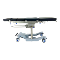
5. Note the mounting position of the motor. Unscrew the
motor [1] from the leg section gear [2] (4 screws [3]) and
remove.
6. Remove the self-adhesive protective sheet [4] from the outer
coupling plate [5].
7. Separate the outer coupling plate [5] from the encoding
bracket [6] (2 screws).
8. Remove 3 pins [7] from the outer coupling plate [5] using a
pin remover.
9. Attention - there is a sliding washer [8] between the coupling
plate [5] and the gear unit [2]. Make sure that the sliding
washer is not lost. Remove the outer coupling plate [5] (3
screws).
10. Remove the two cable covers [9] from the outer coupling
plate [5] (2 screws).
11. Remove the threaded pin [10] from the outer coupling
plate [5].
12. Unscrew the cable housing [11] from the drive unit of the leg
section [2] (2 screws).
13. Remove the cover [12] from the cable housing [11] (1 screw).
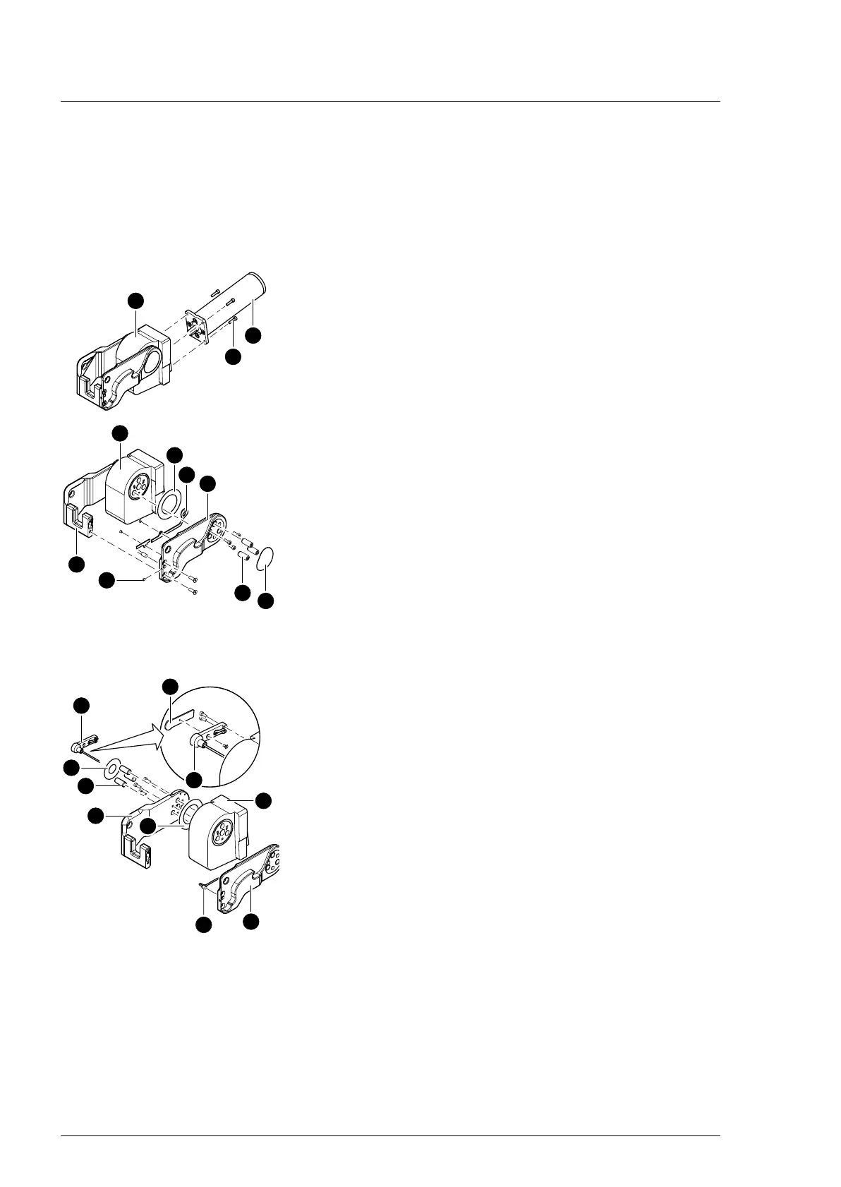
14. Note the cable routing. Unplug the sensor [13] from the outer
coupling plate [5] and the sensor cable from the remaining
parts.
15. Remove the self-adhesive protective sheet [14] from the
inner coupling plate [15].
16. Remove 3 pins [16] from the inner coupling plate [15] using a
pin remover.
17. Attention - there is a sliding washer [17] between the coupling
plate [15] and the gear unit [2]. Make sure that the sliding
washer is not lost. Remove the inner plate (3 screws).
Assembly 1. Remove any adhesive residue from the two coupling plates
and degrease.
2. Check sliding washers and replace if worn or damaged.
3. Push a sliding washer onto the inner lip seal of the gear and
press in the internal coupling plate.
Make sure the sliding washer is properly positioned.
4. Knock 3 pins into the gear unit at the inner coupling plate.