Tabletop cables
100
4990851_002_00 – 2082262 – 2022-01-10
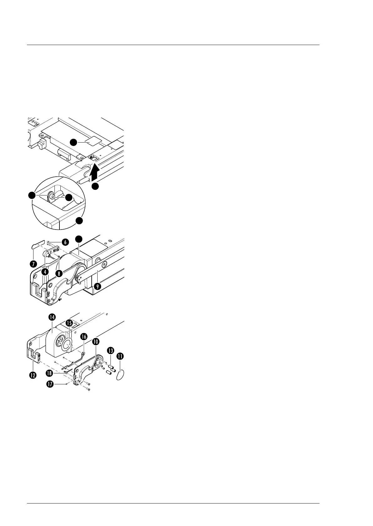
13.6 Hook sensor (W520)
Removal 1. Prepare the operating table (Chapter 5).
2. Disconnect the power supply on the operating table
(Chapter 6.1).
3. Remove the pad plate from the seat section (Chapter 7.2).
Attention: Leave the pad plate on the back section attached
so that the adjustment of the struts is maintained.
4. Remove the self-adhesive protective sheet [1] from the foot-
end and centre opening on the strut.
5. Remove the cable clip [2] (1 screw [3]) and cable ties through
the opening in the seat section bar.
6. Remove the leg section hinge sensor W503/W506
(Chapter 13.3).
7. Note the cable routing. Pull the plug of the sensor cable
W520 from the socket of cable W220/W320 through the
opening in the strut.
8. Guide the plug of the sensor cable through the side opening
in the strut.
9. Unscrew the cable housing [4] from the drive unit of the leg
section [5] (2 screws [6]).
10. Remove the cover [7] from the cable housing [4] (1 screw [8]).
11. Remove the side rail [9] from the seat section (3 screws).
12. Remove the self-adhesive protective sheet [11] from the outer
coupling plate [10].
13. Separate the outer coupling plate [10] from the encoding
bracket [12] (2 screws).
14. Remove 3 pins [13] from the outer coupling plate [10] using a
pin remover.
15. Attention - there is a sliding washer [15] between the coupling
plate [10] and the gear unit [14]. Make sure that the sliding
washer is not lost. Remove the outer coupling cover (3
screws).
16. Remove the two cable covers [16] from the outer coupling
plate [10] (2 screws).
17. Remove the threaded pin [17] from the outer coupling
plate [10].
18. Note the cable routing. Pull the sensor [18] out of the outer
coupling plate and the sensor cable from the remaining parts.
 Loading...