Tabletop electric components
4990851_002_00 – 2082262 – 2022-01-10 47
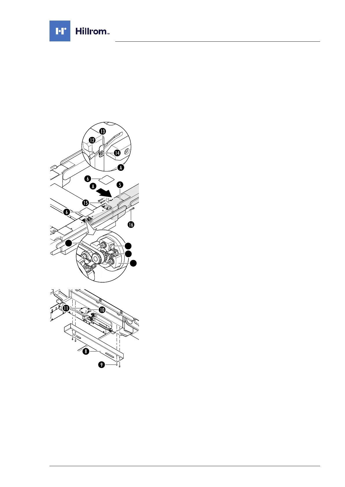
8.4 Drive unit for back section
Attention: the drive unit requires a serial number. Observe
Chapter 1.9 when replacing the drive unit.
Removal 1. Prepare the operating table (Chapter 5).
2. Disconnect the power supply on the operating table
(Chapter 6.1).
3. Remove the pad plate from the seat section and the back
section (Chapter 7.2).
4. Remove the self-adhesive protective sheet [6] from the
head-end and centre opening on the strut.
5. Remove the self-adhesive protective sheet from the centre
opening on the opposite strut.
6. Release the tensioning device [4] for the belts on both back
section drive units [5] (2 screws each).
7. Release the cable clip [2] on a drive unit [5] (1 screw).
8. Slightly loosen the tensioning screw [3] on the clamping
device [4]. Where necessary, ensure that the tensioning
screw on the other clamping device is also slightly loosened.
9. Note the mounting position of the cogged belt. Do not twist
the sprocket on the motor.
Disengage the cogged belt [1] from the drive unit [5].
10. Unscrew the cover [8] of the power chain (4 screws [9], do
not unscrew completely) and disengage.
11. Remove the cover [10] next to the power chain (3 screws [11]).
12. Note the cable routing. Pull the plug of the motor power
supply cable through the opening in the strut.
13. Remove the back section hinge sensor [12] and the retaining
plate [13] (1 screw [14]).
14. Unscrew the drive unit [5] from the strut (2 screws [15] from
above and 2 screws [16] from below).
15. Pull the drive unit [5] with the hinge off the strut and place it
safely on a level work surface.
Assembly 1. Carefully push the drive unit into the strut up to the position
stop and mount (2 screws from above and 2 screws from
below).
Ensure that the cables are not crushed.
2. Attention: Do not interchange the plug connections. Pay
attention to the wiring diagram on page 64.
Restore the original cable routing. Connect the plug of the
motor power supply cable.