Tabletop electric components
48
4990851_002_00 – 2082262 – 2022-01-10
3. Mount the sensor back section hinge and the retaining plate
(1 screw).
4. Attach the cover next to the power chain (3 screws).
5. Position and install the cover for the power chain (4 screws).
6. Check the alignment of the right and left hinges in relation to
each other. The two hinges must be at the same height.
Adjust the hinges if necessary (Chapter 16.2).
7. Switch on the operating table using the switch at the running
gear.
8. Adjust the sensor back section hinge.
The end position of the back section hinge is set on the left
hinge and the zero position of the back section hinge is set on
the right hinge.
a) Carefully shift the back section hinge into the switching
position.
b) The gap between the sensor and hinge must be 0.3 mm to
0.5 mm. Position the sensor accordingly.
9. Switch off the operating table using the switch at the running
gear.
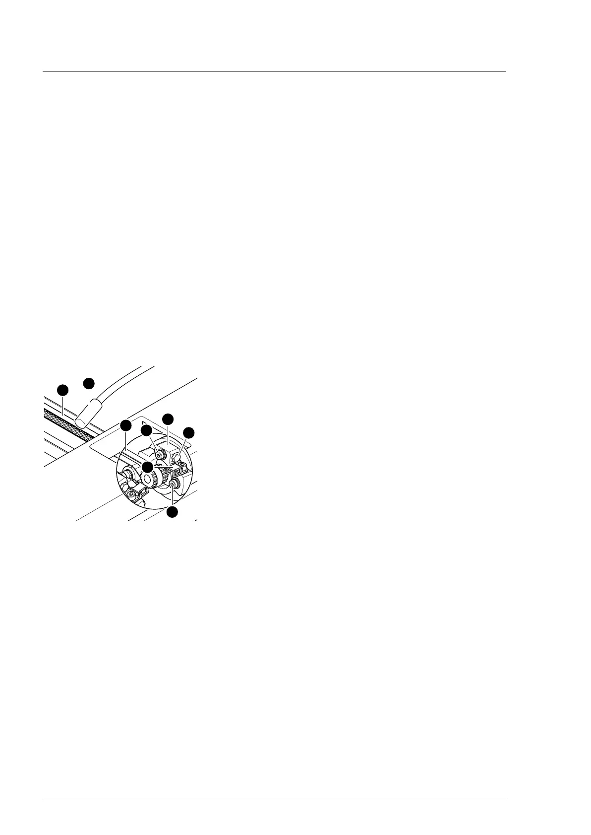
10. Suspend the cogged belt.
Ensure that the cogged belt is properly guided over the
clamp roller. The cogged belts must run parallel.
11. Adjust the cogged belt.
Evenly tension the cogged belt [1] on both sides.
a) Screw in the tensioning screw [3] on both clamping
devices [4].
b) Determine the cogged belt oscillation frequency using a
tension meter device [17] and readjust the cogged belt
tension where necessary using the tensioning screws [3]
(pre-tensioning 49 Hz ± 3 Hz, check 3x in succession).
c) Mount the clamping device [4] for the belts onto both
drive units for the back section hinge (2 screws [18]).
12. Attach the cable clip [2] onto the drive unit (1 screw).
13. Apply new self-adhesive protective sheets to each opening
on both struts.
14. Align struts lengthwise (Chapter 16.1).
15. Mount the pad plates onto the strut (Chapter 7.2).
16. Put the pad in place.
17. Connect the power supply to the operating table
(Chapter 6.2).
18. Update the firmware of the operating table.