8.1 About the Multiplexer
141
8
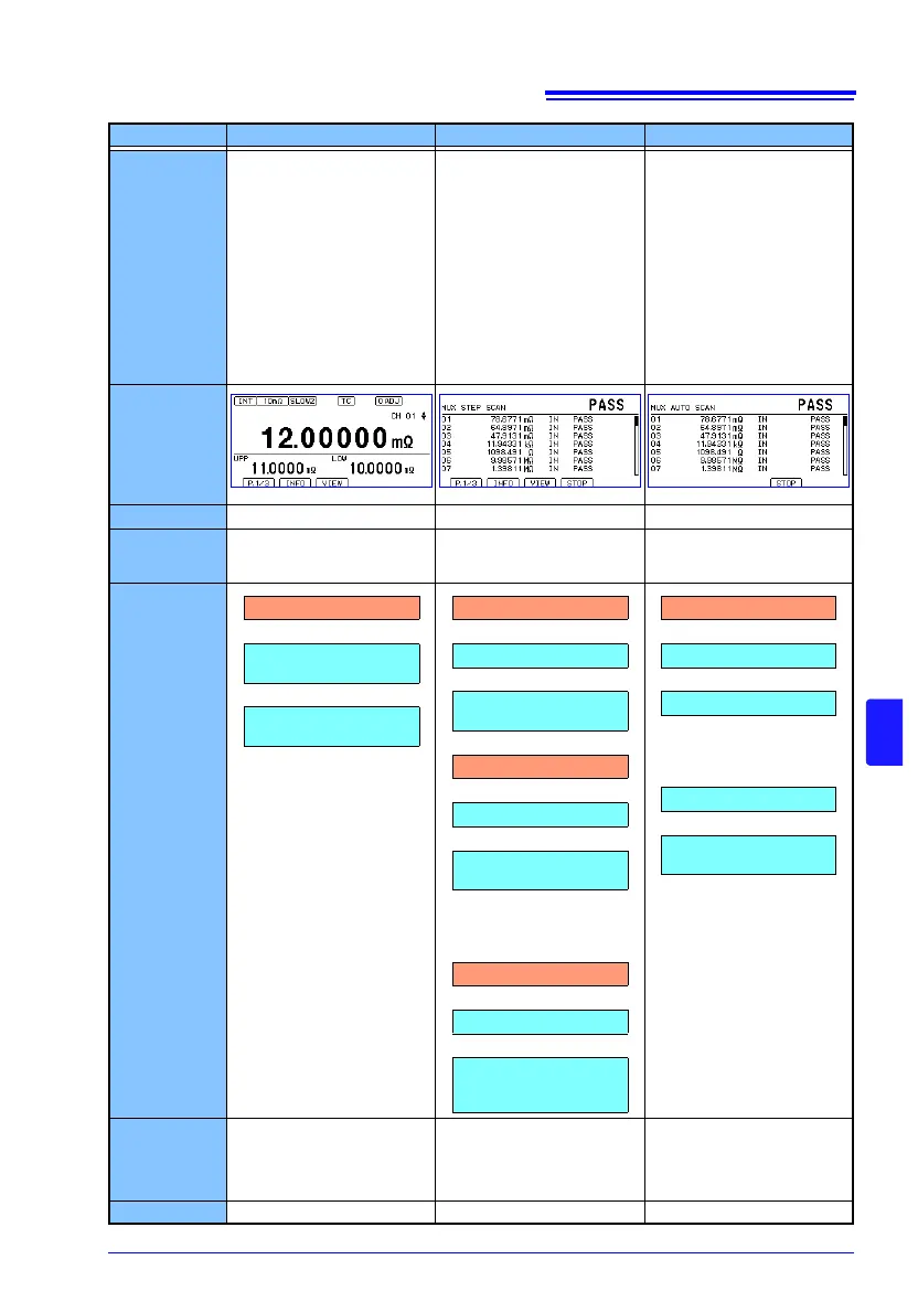
Scan function OFF Step Auto
Overview
The measurement location
can be changed freely.
Example uses
• Using the multiplexer
manually
• Repeating measurement
for particular channels
only
• Switching channels using
external control
The measurement location is
switched according to a pre-
viously set order. A single
TRIG signal causes one
channel to be measured.
Example uses
• Controlling the measure-
ment target during testing,
for example with switches
• Changing operation based
on each channel’s mea-
surement results
The measurement location is
switched according to a pre-
viously set order. A single
TRIG signal causes all chan-
nels to be measured.
Example uses
• Performing scanning at
the fastest possible speed
when controlling the mea-
surement target during
testing is not necessary,
for example for 3-phase
motor windings or net-
work resistors
Measurement
screen
Trigger source
Internal [INT] / External [EXT] External [EXT] only External [EXT] only
Channel
switching
Up/down cursor operation,
commands, LOAD signal
Automatic switching based
on the trigger (channel by
channel)
Automatic switching based
on the trigger (all channels)
TRIG
operation
Acquisition of
each channel’s
measured val-
ue and judg-
ment results
Display,
Communications commands,
EXT I/O
Display,
Communications commands,
EXT I/O
Display,
Communications commands
Total judgment
No Yes Yes
TRIG signal input
Current channel
measurement
Judgment,
EOM signal ON output
TRIG signal input
CH1 measurement
CH1 judgment,
EOM signal ON output
TRIG signal input
CH2 measurement
CH2 judgment,
EOM signal ON output
. . .
TRIG signal input
CHn measurement
CHn judgment,
Total judgment,
EOM signal ON output
TRIG signal input
CH1 measurement
CH2 measurement
. . .
CHn measurement
Total judgment,
EOM signal ON output