10.2 Timing Chart
185
10
Each signal level indicates the ON/OFF state of a contact. When using the current source
(PNP) setting, the level is the same as the EXT I/O pin voltage level. When using the cur-
rent sink (NPN) setting, the high and low voltage levels are reversed.
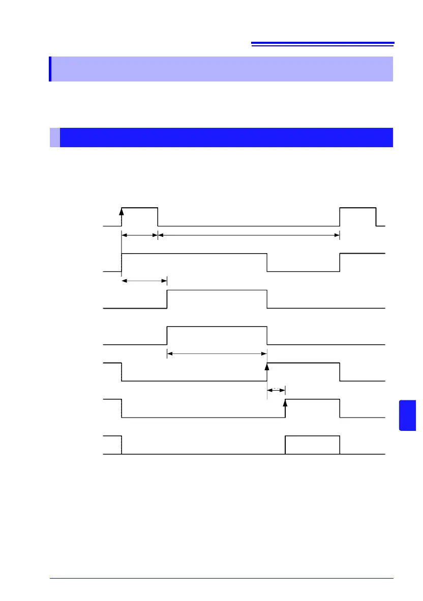
(1) External trigger [EXT] setting (EOM output hold)
10.2 Timing Chart
From Start of Measurement to Acquisition of Judgment Results
TRIG
ON
OFF
t1
Stopped
Delay
t2
Check in progress
t4
INDEX
EOM
OFF
OFF
OFF
ON
ON
ON/OFF
t0
t3
OFF
OFF
OFF
Ap-Applied
Judgment result /BCD: HI, IN, LO, ERR, BCDm-n, RNG_OUT0 to 3
When OVC is OFF
Measurement
processing
Measurement
currents
Measurement
Contact check
Judgment result/
BCD