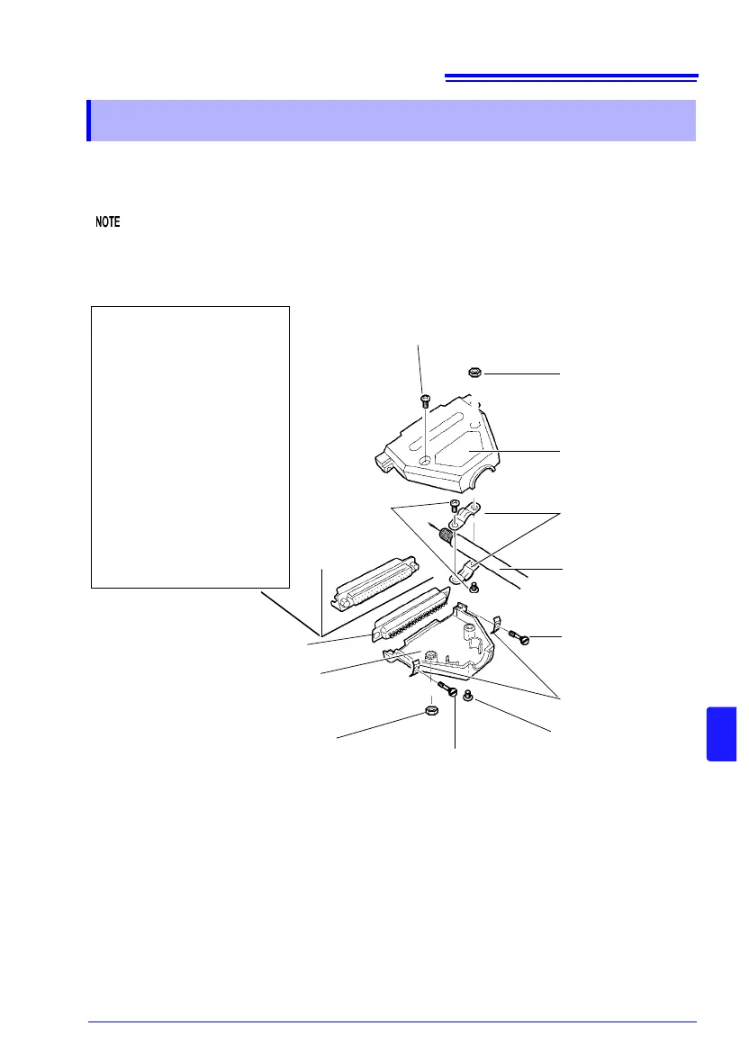
E Nut #4-40UNC
Required tools:
• Screwdriver
• Shielded cable
• Soldering iron
Accessories
• A Cover ................................2
• B Screws (+/-) #4-40UNC
(16.9 mm overall length)...2
• C Screws (+/-) #4-40UNC
(12.6 mm overall length)...2
• D Screws (−) #4-40UNC
(15.0 mm overall length)...2
• E Nuts #4-40UNC.................2
• F Cable Clamps....................2
• G Saddle Washers
(shell protection)...............2
• H Connector .........................1
B Screw (+/-) #4-40UNC (16.9 mm overall length)
A Cover
(Identical halves)
Shielded Cable
(recommended)
D Screw (−) #4-40UNC
(15.0 mm overall
length)
B Screw (+/−) #4-40UNC
(16.9 mm overall length)
E Nut #4-40UNC
D Screw (−) #4-40UNC
(15.0 mm overall length)
A Cover
(Identical halves)
F Cable Clamps
G Saddle Washers
(shell protection)
Assembly Sequence
1. Solder the (shielded) cable wires to the supplied EXT I/O connector (H) pins.
2. Affix the cable clamps (F) on the cable with screws (C).
3. Position the cable clamps (F) to fit properly inside the cover (A).
4. Insert screws (D) through the saddle washers (G).
5. In one half of cover (A), place connector (H), clamps (F), saddle washers (G) and screws (D).
6. Place the other half of cover (A) on top.
7. Affix the halves of the cover (A) together with screws (B) and nuts (E).
Be careful not to overtighten the screws, which could damage the covers.
H Connector
C Screw (+/−)
#4-40UNC
(12.6 mm overall
length)