Appendix 9 Effect of Thermal EMF
A23
Appendix
Thermoelectromotive force
(thermal EMF) is the potential
difference that occurs at the
junction of two dissimilar met-
als, including between the
probe tips and the lead wire of
the measurement target. If the
difference is sufficiently large, it can cause erroneous measurements. (Fig. 1). The ampli-
tude of thermal EMF depends on the temperature of the measurement environment, with
the force generally being greater at higher temperature.
Increasing thermal EMF examples
• The measurement target is a fuse, thermal fuse, thermistor, bimetal, or thermostat.
• The voltage detection lines incorporate a single stable relay as a contact.
• An alligator clip is used as a voltage detection terminal.
• A voltage detection terminal is held by hand.
• There is a large temperature difference between the measurement target and the instru-
ment.
• Wire materials differ between the SENSE A and SENSE B.
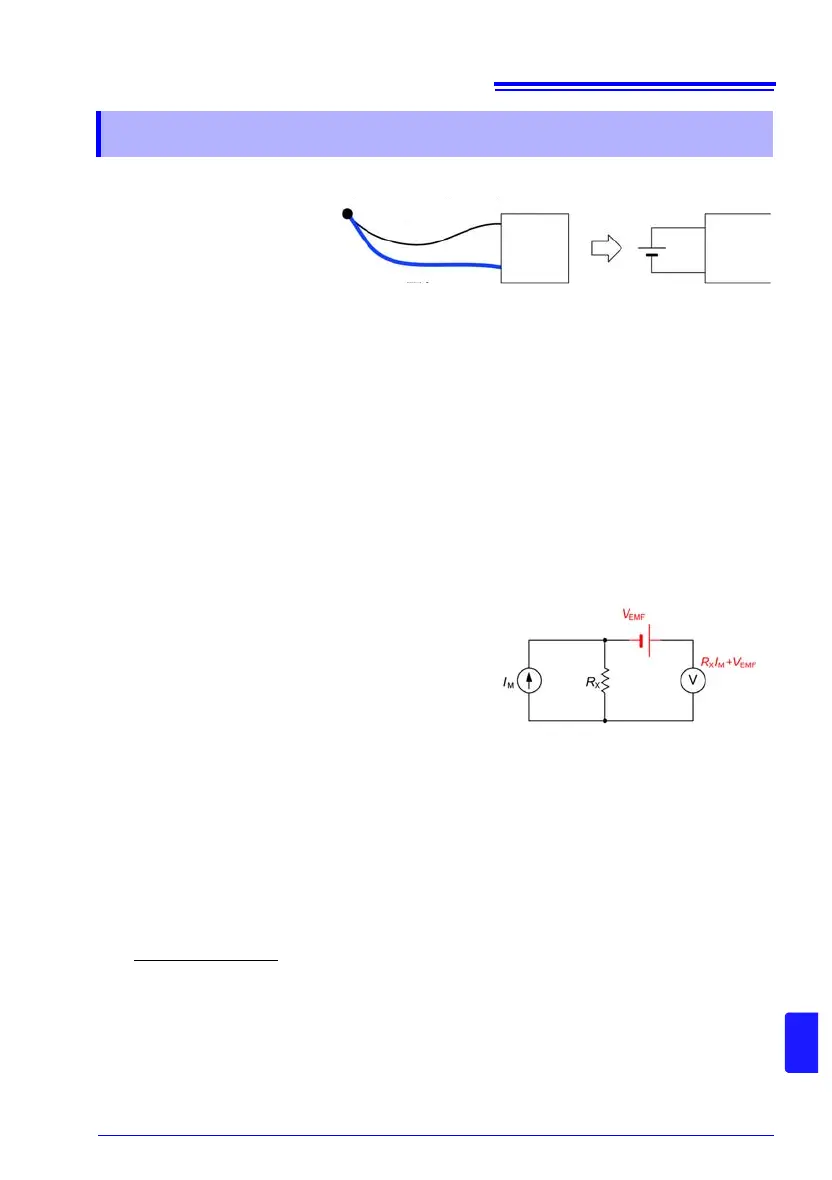
In a resistance measurement, measurement cur-
rent I
M
is applied to measurement target R
X
to
detect voltage drop R
X
I
M
across the target. In a
low resistance measurement, the voltage R
X
I
M
to
be detected is naturally lower due to the low R
X
.
When the detected voltage is low, the measure-
ment will be affected by thermal EMF that is gen-
erated between the measurement target and
probes, and between the cables and the instru-
ment, as well as the voltmeter offset voltage V
EMF
(Fig. 2). If a measurement target is held
by hand, the target will be warmed. A probe will also be warmed by holding it by hand. For
these reasons, even if every care is taken, it will be difficult to control thermal EMF so that it
does not exceed 1 V.
As an example, if a measurement target with an actual resistance of 1m is measured with
a measurement current of 100 mA in an environment with an thermal EMF of 10 V, the
instrument will indicate the following measured value. This is a significant error of 1%
higher than the actual resistance.
The voltmeter offset voltage will also be very large, ranging between 1 V and 10 mV.
This will cause a large low resistance measurement error.
To reduce the effects of thermal EMF, the following actions are possible:
1. Increasing the detection voltage by increasing the measurement current
2. Using zero-adjustment to cancel thermal EMF
3. Changing the detection signal to AC
Appendix 9 Effect of Thermal EMF
Figure 1. Thermal EMF generation
Temperature t
1
Temperature t
2
Metal A
Metal B
This
instrument
t
1
≠ t
2
This
instrument
Figure 2. Thermal EMF generation
1 m × 1 A + 10 V
1 A
=1.01 m