Appendix 9 Effect of Thermal EMF
A24
1. Increasing the detection voltage by increasing the measurement current
In the above thermal EMF example, assume that the measurement current is increased
from 1 A to 100 A. The error will be reduced to 0.01%.
However, it is important to note that RI
2
power is applied.
2. Using zero adjustment to cancel thermal EMF
If current is blocked from being applied to
measurement target R
X
, the voltmeter will
only be supplied with thermal EMF V
EMF
.
However, if the SOURCE terminals are
made open-circuit, a current fault will be
detected and a measured value will not be
displayed. Thus, thermal EMF can be
canceled by shorting the SOURCE lines to
block current flow to R
X
and performing zero
adjustment. (Fig. 3).
See: "3.5 Checking Measured Values" (p.52)
See: "Appendix 6 Zero Adjustment" (p.A7)
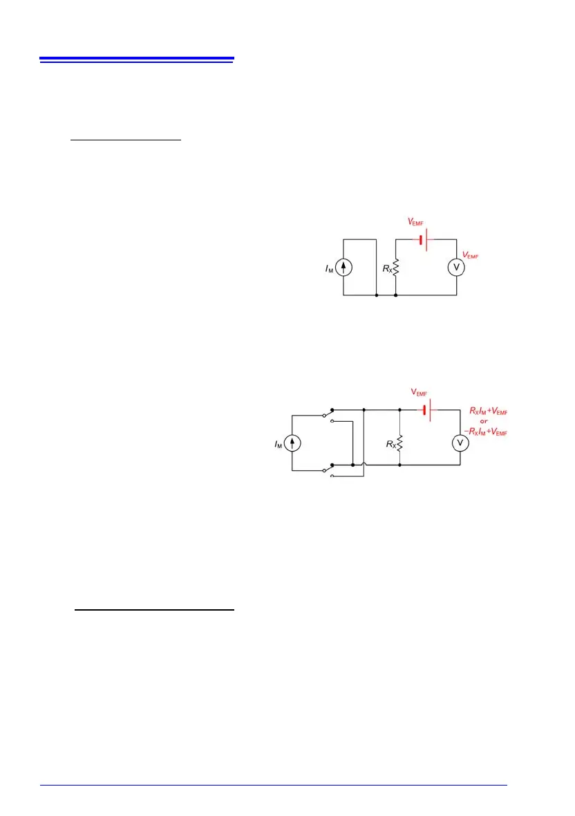
3. Changing the detection signal to
AC
Changing the detection signal to AC is a
fundamental solution. Both the thermal
EMF and voltmeter offset voltage can
be treated as stable DC voltages as
they are viewed for a short period of
time in seconds. This allows frequency
domain separation by changing the
detection signal to AC. The Offset Volt-
age Compensation (OVC) function uses a pulse wave as a measurement current to
eliminate thermal EMF (Fig. 4). Specifically, a resistance value that is not affected by
thermal EMF is obtained by subtracting the voltage detected when the measurement
current is applied in the negative direction from that detected when the current is applied
in the positive direction.
When the measurement target is inductive, some delay must be set (p.84) to allow ade-
quate current flow before starting measurement.
Set the delay so that inductance does not affect measurements.
To fine tune the delay, begin with a longer delay than necessary, then gradually shorten
it while watching the measured value.
1 m × 100 A + 10 V
100 A
=1.0001 m
Figure 3. Using zero adjustment to
block current flow to R
X
Figure 4. EMF cancelation by
current reversal
(R
X
I
M
+ V
EMF
) − (− R
X
I
M
+ V
EMF
)
2I
M
=R
X