Appendix 6 Zero Adjustment
A7
Appendix
Zero adjustment is a function which adjusts the zero point by deducting the residual value
obtained during 0 measurement. For this reason, zero adjustment must be performed
when connection is made to 0 . However, connecting a sample with no resistance is diffi-
cult and therefore is not practical.
In this respect, when performing the actual zero adjustment, create a pseudo connection to
0 and then adjust the zero point.
To create 0 connection state
If an ideal 0 connection is made, the voltage between SENSE A and SENSE B becomes
0 V according to the Ohm's Law of
E = I × R. In other words, if you set the voltage between
SENSE A and SENSE B to 0 V, this gives you the same state of 0 connection.
To perform zero adjustment using the instrument
The instrument uses a measurement fault detection function to monitor the state of connec-
tion between measurement terminals. For this reason, when performing zero adjustment,
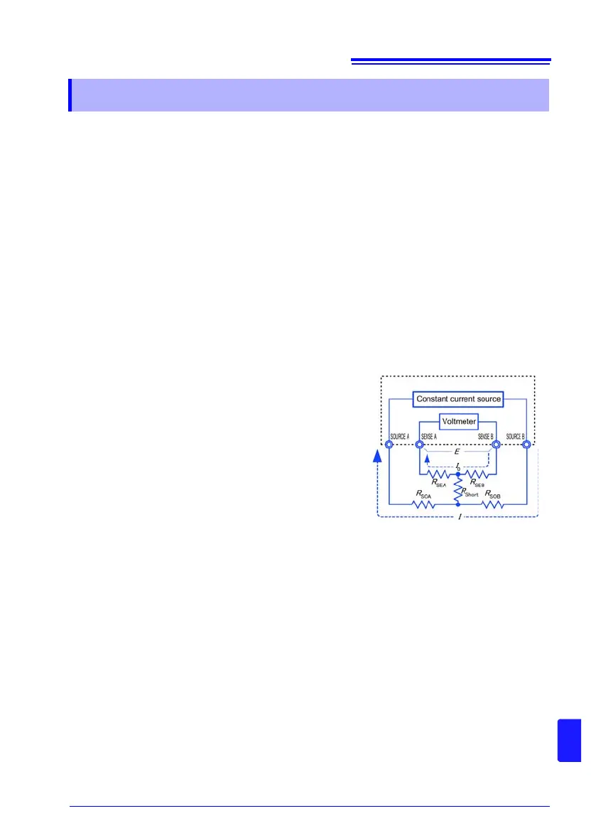
you need to make connections between the terminals appropriately in advance (Fig. 1).
First, short between SENSE A and SENSE B to set
the voltage between SENSE A and SENSE B to 0 V. If
lead resistances
R
SEA
and R
SEB
of the cable are less
than few , there will be no problem. Because the
SENSE terminal is a voltage measurement terminal,
almost no current
I
0
flows. Therefore, in the E = I
0
×
(
R
SEA
+ R
SEB
) formula, I
0
≈ 0 is achieved; if lead resis-
tances
R
SEA
and R
SEB
are less than few , voltage
between SENSE A and SENSE B will become almost
zero.
Next, make connection between SOURCE A and
SOURCE B. This is to avoid display of error when no
measurement current flows through. Lead resistances
R
SOA
and R
SOB
of the cable must be less than the resis-
tance for flowing measurement current.
Furthermore, if the instrument also monitors the con-
nection between SENSE and SOURCE, you need to make connection between SENSE
and SOURCE. If lead resistance
R
Short
of the cable has only few , there will be no prob-
lem.
If you wire in the way described above, measurement current
I flowing out from SOURCE B
will go to SOURCE A but not to the lead of SENSE A or SENSE B. This enables the voltage
between SENSE A and SENSE B to be kept accurately at 0 V, and appropriate zero adjust-
ment becomes possible.
Appendix 6 Zero Adjustment
E = (I
0
× R
SEB
) + (I
0
× R
SEA
)
= (0 ×
R
SEB
) + (0 × R
SEA
)
= 0 [V]
Figure 1.
Pseudo connection to 0