10.1 External Input/Output Connector and Signals
177
10
Before connecting a connector, see "Before Connecting EXT I/O" (p. 13). Use of EXT I/O
enables the following control functionality:
• Measurement start (TRIG) Measurement end (EOM, INDEX)
Acquisition of judgment results
(HI, IN, LO, ERR, T_ERR, T_PASS, T_FAIL)
(T_PASS, T_FAIL, and T_ERR are used only when the scan function is set to auto or
step.)
• Measurement start (TRIG) Measurement end (EOM, INDEX)
Acquisition of measured values (BCD_LOW, BCDm_n, RNG_OUTn)
• Panel load (LOAD0 to LOAD5, TRIG)
• Multiplexer channel specification (MUX, LOAD0 to 5, TRIG)
• General-purpose I/O (IN0, IN1, OUT0, OUT1, OUT2)
The functionality described in "Performing an I/O Test (EXT I/O Test Function)" (p. 215)
provides a convenient way to check external I/O operation.
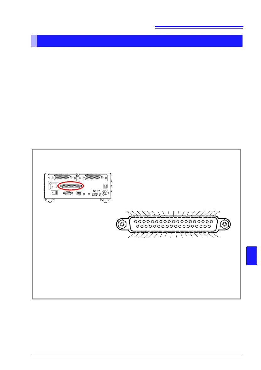
Connector Type and Signal Pinouts
EXT I/O Connector (Instrument Side)
Connector: (Instrument Side)
37-pin D-sub female with #4-40 screws
Mating Connectors:
DC-37P-ULR (solder type) /
DCSP-JB37PR (pressure weld type)
Japan Aviation Electronics Industry Ltd.
12345678910111213141516171819
202122232425262728293031323334353637
TRIG, IN0
BCD_LOW
KEY_LOCK
LOAD1
LOAD3
LOAD5
SCN_STOP
ISO_5V
ISO_COM
ERR
HI, HILO
LO, BCD4-1, RNG_OUT1
T_PASS, BIN0, BCD4-3, RNG_OUT3
T_ERR, BIN2, BCD5-1, BCD1-1
BIN4, BCD5-3, BCD1-3
BIN6, BCD6-1, BCD2-1
BIN8, BCD6-3, BCD2-3
OUT0, BCD7-1, BCD3-1
OUT2, BCD7-3, BCD3-3
0ADJ
CAL
LOAD0
LOAD2
LOAD4
MUX
PRINT, IN1
ISO_COM
EOM
INDEX, BCD4-0, RNG_OUT0
IN
OB, BCD4-2, RNG_OUT2
T_FAIL, BIN1, BCD5-0, BCD1-0
BIN3, BCD5-2, BCD1-2
BIN5, BCD6-0, BCD2-0
BIN7, BCD6-2, BCD2-2
BIN9, BCD7-0, BCD3-0
OUT1, BCD7-2, BCD3-2