Appendix 13 Making Your Own Measurement Leads, Making Connections to the Multiplexer
A29
Appendix
Recommended Measurement Lead Specifications
Example: UL1354, UL1631, UL1691
Before Wiring
See: "Appendix 7 Unstable Measured Values" (p. A12)
• Use shielded wiring for
measurement leads and
connect the shield potential
to the instrument’s GUARD
terminal. Use the GUARD
potential to shield probes
and near the measurement
target.
Twist the four wires together
and keep loop area small.
• Keep measurement
leads and the mea-
surement target
away from high-cur-
rent, high-voltage,
and high-frequency
wires (withstanding
voltage testers,
power cords, motors,
solenoid valves).
The phenomenon of induction becomes pronounced in the 10 m and 100 m ranges
(when the measurement current is set to 1 A). Variations in lead position or shape may
cause measured values to vary. Exercise care to prevent positions and shapes from
changing. Additionally, measurement leads and measurement targets should be kept as
far as possible from metallic objects.
• When using two or more RM3545 units, do not group the wires from multiple instruments
together. Induction phenomena may cause measured values to become unstable or the
contact check circuit to generate erroneous results.
Appendix 13 Making Your Own Measurement
Leads, Making Connections to the
Multiplexer
Conductor resistance
500 m/m or less
Capacitance
150 pF/m or less
Cable dielectric material
Polyethylene (PE), Teflon* (TFE), polyethylene foam (PEF)
Insulation resistance at least 100 G (RMS)
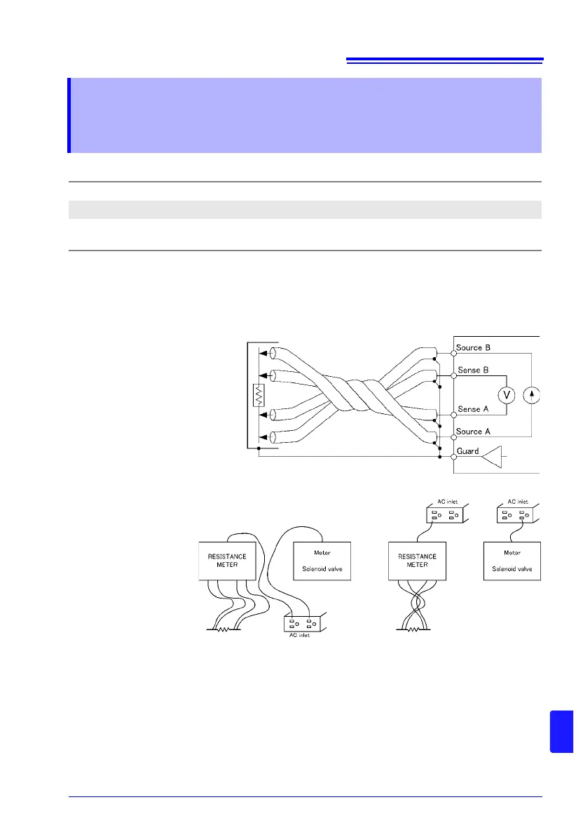
Wiring Diagram
Static shielding
Poor example Good example
Power supply on a separate circuit
The same inlet
is used.
Measurement leads are
close to power supply wires.